Wireless Charging
Development of a Wireless Electric Vehicle Charging System Using Resonant Inductive Coupling
Department of Electrical and Electronic Engineering, Petroleum Training Institute (PTI), Effurun, Delta State, Nigeria
Published September2026
Abstract
Because of the increasing number of electric vehicles (EVs) being adopted, there has been more interest in wireless charging as a substitute for plug-in systems. This study describes the design and development of a wireless EV charging system which uses resonant inductive coupling, meaning that electrical power is transferred between the transmitting and receiving coils by means of magnetic resonance at the same resonant frequency. The system consists of a transmitting coil that is connected to an AC power source and a receiving coil that is built into the vehicle's battery charging circuit. Experiments were carried out at coil separation distances ranging from 5 to 10 cm and under various alignment situations. The greatest charging efficiency was obtained when the coils were properly aligned. As the separation was increased from 5 cm to 10 cm, the efficiency dropped, and a comparable decrease was seen when the receiving coil was moved from the centre of the transmitting coil. Power was still transferred under the misalignment conditions that were tested, even though the amount of power transferred decreased as the position of the coil became less favourable. The findings show that resonant inductive coupling can be employed for short-range wireless EV charging, especially in cases where the transmitting and receiving coils can be kept close together and well aligned. The experiments were carried out in controlled laboratory conditions and did not take into account factors such as the position in which the vehicle is parked, variations in temperature, the materials surrounding the system, or long-term degradation of the components. It would be necessary to carry out testing under more realistic operating conditions in order to find out how these factors influence the system's efficiency and reliability in actual EV applications.
Keywords: wireless power transfer (WPT); resonant inductive coupling; electric vehicle charging; energy efficiency; smart mobility
1Introduction
The growing use of electric vehicles (EVs) has increased the need for charging systems that are efficient and convenient to use. Plug-in charging remains the most common method, but it depends on a physical connection between the vehicle and the charging equipment. Charging cables and connectors are handled repeatedly and can wear over time. At outdoor charging points, they are also exposed to rain, dust, heat, and other environmental conditions. For some EV users, especially at public charging stations, connecting and disconnecting the cable each time may be inconvenient. These issues have led to increasing interest in charging methods that can transfer electrical power without a direct cable connection.
One possible alternative is Wireless Power Transfer (WPT). The system sends electrical energy through an electromagnetic field between a transmitting coil and a receiving coil rather than a cable. For example, in an electric vehicle (EV) charging system, the transmitting coil can be embedded in a charging pad on the ground and the receiving coil can be embedded under the vehicle. When the vehicle is parked over the pad, energy can be transferred across the air gap between the two coils. Removing the need for a physical connector could make the charging process easier to use and may also reduce some of the problems associated with exposed electrical contacts.
Several WPT methods have been investigated, but resonant inductive coupling is particularly suitable where a reasonable amount of power needs to be transferred across an air gap. In this arrangement, the transmitting and receiving circuits are tuned to operate at, or close to, the same resonant frequency. When the system is properly tuned, resonance can improve the transfer of energy between the coils. The actual performance, however, depends on several factors. Coil design, operating frequency, compensation components, separation distance, and the level of magnetic coupling between the coils can all influence the amount of power reaching the receiving side.
The position of the coils is another practical concern. An EV driver may not park in exactly the same position over a charging pad every time. A small sideways displacement between the two coils can reduce their magnetic coupling and, as a result, affect the transferred power. The vertical distance between the coils also matters. As the air gap increases, less of the magnetic field produced by the transmitting coil links effectively with the receiving coil. This can lead to a reduction in charging performance. A system that works well when the coils are perfectly aligned may not perform in the same way when the vehicle is slightly off-centre.
Previous studies have demonstrated that resonant inductive coupling can be used for wireless EV charging. However, many experimental investigations are carried out under carefully controlled conditions, where the coil position and separation are kept almost constant. Such conditions are useful for evaluating the basic behaviour of a system, but they may not represent what happens during normal vehicle parking. In a practical installation, some variation in vehicle position is almost unavoidable. The relationship between charging efficiency, coil separation, and alignment is thus worth examining, particularly when the distance between the vehicle and the charging pad is increased.
In this work, a resonant inductive wireless EV charging system is designed and experimentally evaluated. The proposed system is comprised of a transmitting coil connected to the power source and a receiving coil connected to the vehicle-side charging circuit. The coil separation distance was altered from 5 to 10 cm and tests were carried out. Additional measurements are performed with different coil alignment settings to study the effects of position variations on the system. The main performance measures are transferred power, output voltage, output current, and overall charging efficiency.
The purpose of the study is not to claim the development of a complete commercial EV charging station. Instead, it provides an experimental assessment of the operating behaviour of a resonant inductive charging arrangement at a smaller prototype scale. Practical factors such as component selection, electrical safety, cost, and the possibility of scaling the design to higher charging power are also considered. Testing the system under both aligned and slightly misaligned conditions should give a more realistic picture of its performance and help identify the conditions in which resonant inductive coupling works effectively, as well as those where its limitations become significant.
1.1Objective of the research
The overall aim of this study is to develop and experimentally evaluate a wireless electric vehicle (EV) charging system based on resonant inductive coupling. The study focuses on the ability of the system to transfer electrical power across an air gap and how its performance changes with coil alignment, separation, and other design parameters.
The specific objectives are to:
(a) Design and develop a wireless EV charging system using resonant inductive coupling for efficient power transfer.
(b) Evaluate the performance and charging efficiency of the developed system under different coil alignment conditions and separation distances.
(c) Investigate the effects of coil design, resonant frequency tuning, and inverter configuration on the efficiency of wireless power transfer.
(d) Assess the scalability and practical suitability of the proposed charging system for small- to medium-sized electric vehicles.
(e) Examine the potential economic and environmental benefits, as well as the practical limitations, associated with the use of resonant inductive coupling for EV charging.
1.2Justification for the study
The increasing use of electric vehicles (EVs) has created a need for charging systems that are convenient, safe, and reliable. Conventional plug-in charging depends on cables and connectors, which may wear with repeated use and can be inconvenient in some charging environments.
Resonant inductive wireless power transfer offers an alternative by transferring energy without a direct electrical connection. However, its efficiency can be affected by coil alignment, separation distance, resonance tuning, and system design. Many existing studies focus on controlled conditions, with less attention given to changes that may occur during normal vehicle parking.
This study is justified by the need to experimentally evaluate these effects. A wireless EV charging prototype will be tested at separation distances of 5–10 cm and under different coil alignment conditions. The results will be used to assess power transfer, charging efficiency, and the practical limitations of the proposed system.
2Literature review
Wireless power transfer (WPT) has developed from early experiments in electromagnetic induction into a practical technology for several applications, including electric vehicle (EV) charging. Early work by Nikola Tesla helped establish the basic principles of wireless power transmission. More recent research has focused on transferring useful amounts of power over short distances while maintaining acceptable efficiency and safety.
Resonant inductive coupling (RIC) has received considerable attention because it allows energy to be transferred between two coils without a direct electrical connection. The transmitter and receiver are tuned to a similar resonant frequency, allowing energy to be transferred through a magnetic field. Kurs et al. (2007) demonstrated that magnetic resonance could achieve effective power transfer over distances greater than conventional inductive systems. Their work contributed to the development of modern resonant wireless power systems.
Subsequent studies have shown that system performance depends strongly on coil design, operating frequency, compensation networks, and the degree of coupling between the coils. Sample et al. (2011) examined magnetically coupled resonators and methods for maintaining power transfer when operating conditions change. Hui et al. (2014) also identified misalignment, electromagnetic interference, and thermal effects as important challenges in wireless power transfer. These findings suggest that achieving high efficiency under controlled conditions is relatively straightforward compared with maintaining similar performance when the coils are displaced.
For EV applications, coil alignment and separation are particularly important. As the distance between the transmitter and receiver increases, magnetic coupling generally decreases, which can reduce transferred power and system efficiency. Lateral misalignment can produce a similar effect. Compensation structures such as series-series (S-S) and LCC networks have consequently been investigated to improve power transfer and reduce reactive losses (Zhang & Mi, 2016). Ferrite materials and shielding techniques have also been used to guide the magnetic field and limit unwanted electromagnetic emissions.
Research has also moved beyond basic power transfer toward intelligent charging and grid integration. Wireless charging can potentially be combined with communication, load management, and vehicle-to-grid (V2G) technologies. However, these developments also increase system complexity and cost. For smaller or developing charging applications, a simpler system may be more practical if acceptable charging efficiency can still be achieved.
Despite the progress made in WPT research, practical challenges remain. Maintaining efficient power transfer during coil misalignment, increasing the allowable air gap, controlling system temperature, and keeping the overall cost reasonable are still important considerations. These issues are particularly relevant to EV charging because the vehicle cannot always be positioned precisely over the transmitting coil.
Based on these gaps, this study focuses on the development and experimental evaluation of a resonant inductive wireless EV charging prototype. The investigation considers coil separation distances of 5–10 cm and different alignment conditions. Particular attention is given to the relationship between coil position, transferred power, and charging efficiency. The results are expected to provide practical information on the operating conditions and limitations of a relatively simple wireless EV charging system.
3Research methodology
3.1System architecture
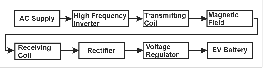
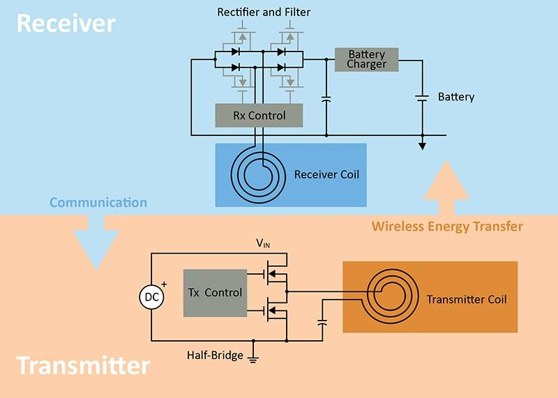
The wireless EV charging system was modelled in LTspice using resonant inductive coupling. The model includes an AC supply, high-frequency switching circuit, transmitting and receiving coils, compensation capacitors, rectifier, filter, and a resistive load representing the vehicle battery.
The two coils are electrically isolated but magnetically coupled. The primary circuit produces the alternating magnetic field, which induces a voltage in the secondary coil. The received AC power is then rectified and filtered to obtain the DC output.
3.2Resonant coil and circuit design
The transmitting and receiving coils were modelled as coupled inductors. Coil inductance, coil resistance, compensation capacitance, operating frequency, and coupling coefficient were considered in the design.
The resonant frequency was calculated using:
where:
- f₀ = resonant frequency (Hz)
- L = coil inductance (H)
- C = compensation capacitance (F)
A Series-Series (SS) compensation topology was used for the primary and secondary circuits. The coupling coefficient was varied from 0.20 to 0.40 to examine the effect of magnetic coupling on power transfer.
3.3Simulation procedure
The complete circuit was simulated in LTspice using transient and AC sweep analyses. Transient analysis was used to observe the voltage and current waveforms and the transition to steady-state operation.
For each coupling coefficient, the output power and efficiency were obtained from the simulation. An AC sweep was also performed around the nominal operating frequency of 85 kHz to identify the resonant region and observe the frequency response.
Power was calculated using:
where P is power (W), V is voltage (V), and I is current (A).
The power-transfer efficiency was calculated as:
where Pout is the power delivered to the load and Pin is the input power to the charging circuit.
The results were then compared to assess how changes in coupling and operating frequency affect the simulated output power and efficiency.
The system was tested under varying conditions to observe its behavior and efficiency. The following parameters were investigated:
- 1. Distance between transmitting and receiving coils
- 2. Alignment between coils
- 3. Power transfer efficiency at different loads
The coils were positioned at distances ranging from 5 cm to 10 cm, and slight misalignments were intentionally introduced to simulate real-world vehicle positioning.
3.4Coil design calculations
The resonant frequency of the LC circuit is given by:
Where:
- f = Resonant frequency
- L = Inductance of the coil
- C = Capacitance of the resonant capacitor
This equation ensures both transmitter and receiver operate at the same resonant frequency for maximum power transfer.
Where:
- L = inductance (H)
- N = number of turns of the coil
- μ (mu) = magnetic permeability
- A = cross-sectional area of the coil (m²)
- l = length of the coil (m)
This equation is used to estimate the inductance of the coil, which is a key factor in determining system performance.
3.5Magnetic field analysis
Where:
- k = coupling coefficient (0 to 1)
- M = mutual inductance (H)
- L₁ = inductance of transmitting coil (H)
- L₂ = inductance of receiving coil (H)
The coupling coefficient indicates how effectively energy is transferred between the coils. A higher value means better efficiency.
Where:
- V = induced voltage (Volts)
- N = number of turns of the coil
- Φ (Phi) = magnetic flux (Weber)
- dΦ/dt = rate of change of magnetic flux
4Results and discussion
The proposed wireless electric vehicle (EV) charging system was simulated in LTspice using a Series-Series (SS) compensation topology. The main focus was to examine how the coupling coefficient affects power transfer and efficiency, and to observe the frequency response of the system around the intended operating frequency of 85 kHz.
4.1Simulation parameters
The simulation was carried out using the parameters shown in Table 1. Both the transmitting and receiving coils were assigned an inductance of 220 µH, while 15 nF capacitors were used for series compensation. The coil resistance was set to 0.5 Ω for both sides, and a 20 Ω resistive load was used to represent the charging load.
| Parameter | Symbol | Value |
|---|---|---|
| Supply Voltage | Vs | 230 V (AC) |
| Operating Frequency | f0 | 85 kHz |
| Primary Inductance | L1 | 220 µH |
| Secondary Inductance | L2 | 220 µH |
| Compensation Capacitors | C1, C2 | 15 nF |
| Coil Resistance | R1, R2 | 0.5 Ω |
| Load Resistance | RL | 20 Ω |
| Coupling Coefficient | (k) | 0.2–0.4 |
4.2Transient response
The transient simulation showed an initial oscillatory response before the circuit settled into a more regular periodic waveform. Such behaviour is expected when the resonant circuit is first energized, since energy builds up between the inductive and capacitive elements.
After the initial transient period, the voltage and current waveforms became relatively stable. This suggests that the compensation network was able to establish sustained resonant operation under the selected conditions. The response also indicates that the system is sensitive to the initial operating conditions, which is typical of resonant wireless power transfer circuits.
4.3Effect of coupling coefficient on power transfer
The coupling coefficient was varied from 0.20 to 0.40 to examine its effect on the charging performance. The simulated results are presented in Table 2.
| Coupling Coefficient k | Output Power (W) | Efficiency (%) |
|---|---|---|
| 0.20 | 820 | 67 |
| 0.30 | 1400 | 79 |
| 0.40 | 2150 | 89 |
A clear increase in output power was observed as the coupling coefficient increased. At k = 0.20, the system delivered approximately 820 W with an efficiency of 67%. Increasing the coupling coefficient to 0.30 raised the simulated output power to about 1,400 W, while efficiency increased to 79%. At k = 0.40, the output reached approximately 2,150 W and the efficiency increased to 89%.
The trend is consistent with the expected behaviour of magnetically coupled resonant coils. A higher coupling coefficient means stronger magnetic interaction between the two coils and, consequently, greater flux linkage in the receiving coil. Less energy is likely to be lost during transfer, which helps explain the improvement in efficiency.
The results also show why coil positioning is an important issue in practical EV wireless charging. A lower coupling coefficient may occur when the air gap increases or when the transmitter and receiver coils are not properly aligned. Although the present work does not experimentally measure these physical effects, the simulation results provide an indication of how changes in magnetic coupling can influence charging performance.
4.4Frequency response
An AC sweep was performed around the selected operating frequency to examine the frequency-dependent behaviour of the charging system. The response showed a noticeable peak close to 85 kHz, indicating that the system reaches its strongest response within this region.
Away from the resonant region, the transferred power decreased. This behaviour is expected because the inductive and capacitive reactances no longer cancel as effectively when the operating frequency moves away from resonance. The result highlights the need for appropriate frequency tuning in resonant wireless charging systems.
The frequency response also suggests that maintaining the operating point near resonance is important for achieving efficient power transfer. In a practical EV charging system, however, the optimum frequency may shift because of changes in coil alignment, separation, component tolerances, or load conditions. A fixed-frequency design may consequently experience some reduction in performance under changing operating conditions.
4.5Overall discussion
The simulation results indicate that both resonance and magnetic coupling have a strong influence on the performance of the proposed wireless charging system. Increasing the coupling coefficient from 0.20 to 0.40 increased the simulated efficiency from 67% to 89%, while output power increased from 820 W to 2,150 W.
These results are encouraging, but they should be interpreted within the limits of the simulation model. The study does not account for all practical losses that could occur in a physical EV charging system, including detailed coil geometry, temperature-dependent resistance, electromagnetic interference, switching losses, and mechanical misalignment. The reported efficiency values should consequently be regarded as simulation results rather than direct predictions of real-world charging efficiency.
Even with these limitations, the results show that resonant inductive coupling can provide substantial power transfer without a direct electrical connection between the charging coils. The improvement observed with increasing coupling also points to the importance of coil alignment and separation in future work. More detailed simulations could examine specific air gaps and misalignment conditions to establish a clearer relationship between physical coil position, coupling coefficient, output power, and efficiency.
5Conclusions
The study developed and evaluated an LTspice model of a wireless electric vehicle charging system based on resonant inductive coupling. The simulation shows that power can be transferred between the transmitting and receiving coils without a direct electrical connection.
The results indicate that coupling has a clear effect on system performance. As the coupling coefficient increased from 0.20 to 0.40, simulated output power increased from 820 W to 2,150 W, while efficiency improved from 67% to 89%. The frequency sweep also showed a strong response around 85 kHz, suggesting that proper frequency tuning is important for maintaining effective power transfer.
Although the results are encouraging, they should be interpreted within the limits of simulation. Actual performance is likely to be affected by coil alignment, separation, switching losses, coil geometry, temperature, and other practical factors that are not fully represented in the model.
Overall, resonant inductive coupling appears to be a suitable approach for wireless EV charging. Future work should focus on modelling different coil geometries and misalignment conditions, followed by experimental validation and investigation of higher-power and smart-grid-connected charging systems.
References
- [1]Kober T, Schiffer HW, Densing M, Panos E. Global energy perspectives to 2060 – WEC's World Energy Scenarios 2019. Energy Strategy Reviews. 2020;31:100523. https://doi.org/10.1016/j.esr.2020.100523
- [2]Kurs A, Karalis A, Moffatt R, Joannopoulos JD, Fisher P, Soljačić M. Wireless power transfer via strongly coupled magnetic resonances. Science. 2007;317:83–86. https://doi.org/10.1126/science.1143254
- [3]Sample AP, Meyer DT, Smith JR. Analysis, experimental results, and range adaptation of magnetically coupled resonators for wireless power transfer. IEEE Transactions on Industrial Electronics. 2011;58:544–554. https://doi.org/10.1109/TIE.2010.2046002
- [4]Hui SYR, Zhong W, Lee CK. A critical review of recent progress in mid-range wireless power transfer. IEEE Transactions on Power Electronics. 2014;29:4500–4511. https://doi.org/10.1109/TPEL.2013.2249670
- [5]Budhia M, Covic GA, Boys JT. Design and optimization of circular magnetic structures for lumped inductive power transfer systems. IEEE Transactions on Power Electronics. 2011;26:3096–3108. https://doi.org/10.1109/TPEL.2011.2143730
- [6]Zhang W, Mi CC. Compensation topologies of high-power wireless power transfer systems. IEEE Transactions on Vehicular Technology. 2016;65:4768–4778. https://doi.org/10.1109/TVT.2015.2454292
- [7]Rahman MM, Shanto MSI, Rani T, Paul L. A comprehensive review of wireless power transfer methods, applications, and challenges. Engineering Reports. 2024;6. https://doi.org/10.1002/eng2.12951
- [8]Yilmaz M, Krein PT. Review of the impact of vehicle-to-grid technologies on distribution systems and utility interfaces. IEEE Transactions on Power Electronics. 2013;28:5673–5689. https://doi.org/10.1109/TPEL.2012.2227500