Energy Storage Systems
Numerical Investigation of Packing Structure and Bed Geometry Effects on Heat Transfer in Granite Rockbed Thermal Energy Storage Systems
Department of Mechanical/Production Engineering, Abubakar Tafawa Balewa University, Bauchi, Nigeria
Published October 2026
Abstract
The thermal performance of a packed rockbed thermal energy storage system depends not only on particle properties but also on the spatial arrangement and overall geometry of the storage bed. This paper extracts the thermal and packing-structure component of an MSc numerical study carried out using ANSYS Fluent 19.2. Equal-volume cubical, cylindrical and conical/truncated-conical rockbed configurations were investigated using granite and air. The simulations used an inlet temperature of 500 K, a mass flow rate of 0.15 kg/s for the reported geometry comparison, and a particle-size range of 20–60 mm for the broader study. For the 40 mm particle comparison, the reported heat-transfer rates were 16.599 kW for the cube, 18.108 kW for the cylinder and 19.617 kW for the cone. The conical configuration therefore produced the largest reported heat-transfer rate among the three 40 mm cases, while the cube produced the lowest. The temperature contours show the development of a thermal front, with the hot region advancing from the inlet toward the colder downstream region. The reported outlet-temperature series decreased from 500 K at the start of the plotted charging history to 415 K at 3600 s. The results demonstrate that bed geometry and packing arrangement can materially alter thermal response and should be evaluated together with hydraulic resistance when designing rockbed thermal storage.
Keywords: rockbed thermal energy storage; packing structure; bed geometry; heat transfer; thermal front; granite; CFD
1Introduction
Packed rockbeds store thermal energy as sensible heat in solid particles while a flowing heat-transfer fluid charges or discharges the bed. Although particle size is important, the spatial distribution of particles and the macroscopic shape of the bed determine the flow path, local velocity field, contact area and progression of the thermal front. Consequently, two beds having the same storage volume and material can exhibit different thermal responses when their packing or overall geometry differs.
The present paper focuses on the second major theme of the MSc project: the effect of packing structure and bed geometry on thermal performance. The central question is how the cubical, cylindrical and conical configurations used in the project differ in temperature distribution and heat-transfer rate under comparable conditions.
2Materials and methods
2.1Bed configurations
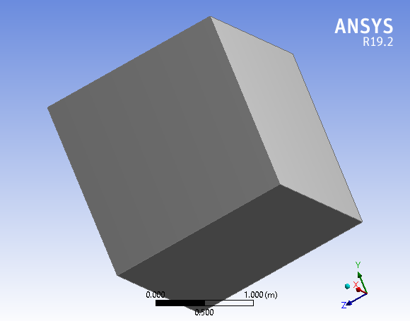
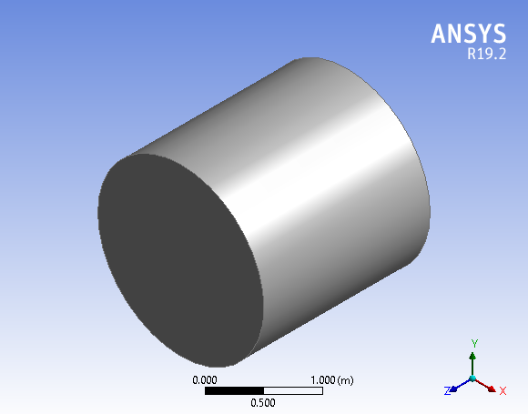
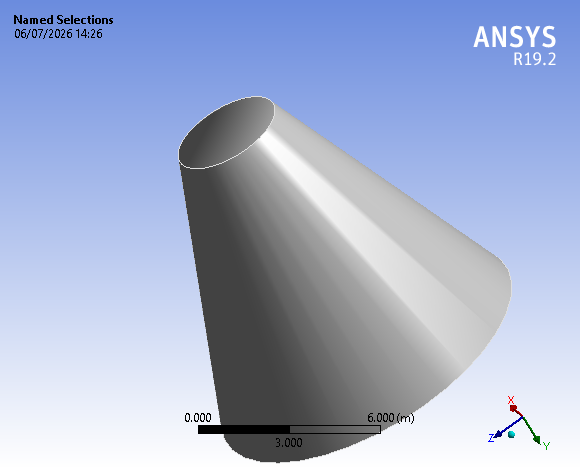
The project considered cubical, cylindrical, conical/truncated-conical and irregular configurations. For the principal geometry comparison, the bed volumes were designed to be equal so that differences in thermal behaviour could be attributed primarily to geometry and packing rather than storage volume. The three bed geometries are shown in Figure 1, Figure 2 and Figure 3.
2.2Operating conditions
The operating conditions of the simulations are listed in Table 1.
| Parameter | Value/condition |
|---|---|
| Storage material | Granite |
| Heat-transfer fluid | Air |
| Reference inlet temperature | 500 K |
| Reference inlet velocity | 5 m/s |
| Reference simulation time | 3600 s |
| Particle diameters considered | 20, 30, 40, 50 and 60 mm |
| Porosities considered | 0.20, 0.30, 0.35, 0.40 and 0.45 |
| Principal geometry comparison | Cube, cylinder and cone |
| Equal-volume condition | Yes, for the compared bed geometries |
2.3Thermal model
The thermal model accounts for transient energy storage in the granite and convective heat exchange with the air. For the solid phase, the project used the heat-conduction relation in Equation (1).
The fluid and solid energy equations were treated as coupled through the fluid–solid heat-transfer process. The heat-transfer rate was evaluated from Equation (2):
where ṁ is the mass flow rate, cp,f the specific heat capacity of air, and Tin and Tout the inlet and outlet temperatures.
3Results and discussion
3.1Numerical convergence
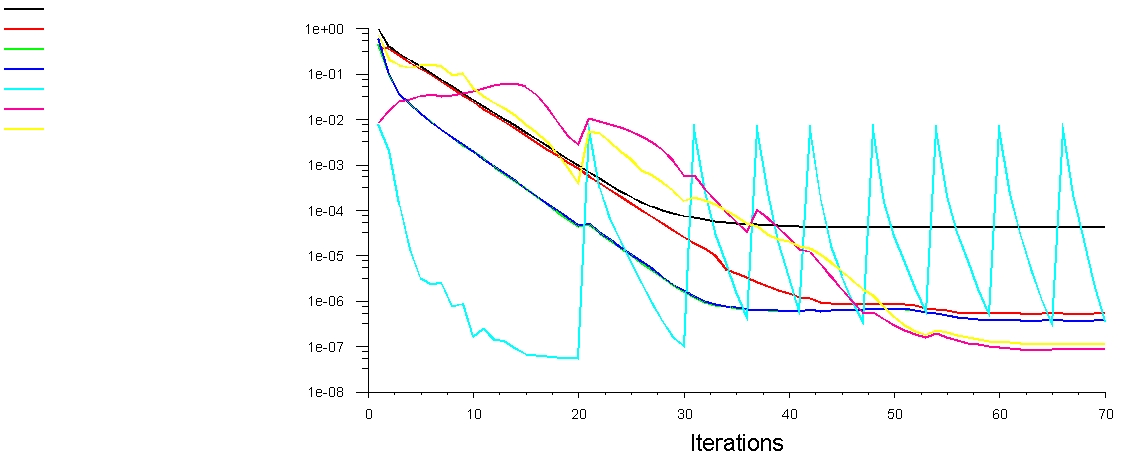
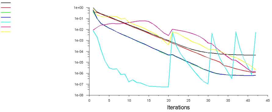
The project convergence plots (Figure 4 and Figure 5) show substantial reduction in continuity, momentum and energy residuals. The energy residual displays transient oscillations in some cases, consistent with repeated solution of the energy field at successive time steps. The report considered the monitored solutions sufficiently converged for evaluating temperature, pressure and flow behaviour.
3.2Temperature contours and thermal-front development
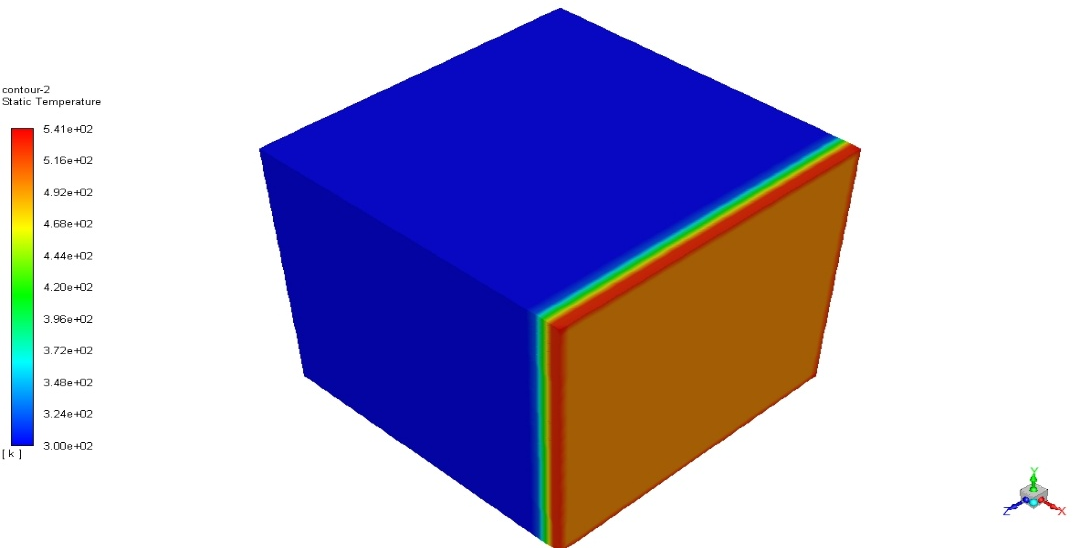
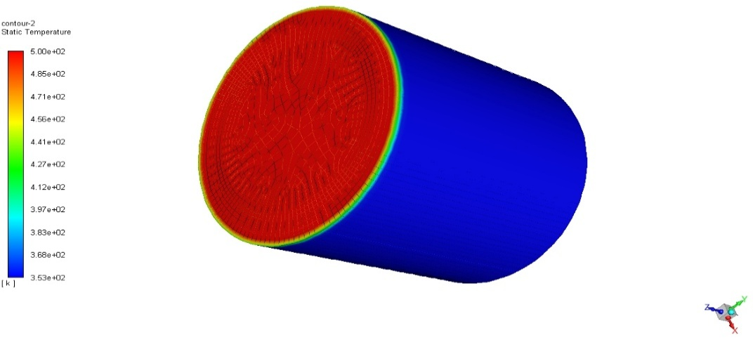
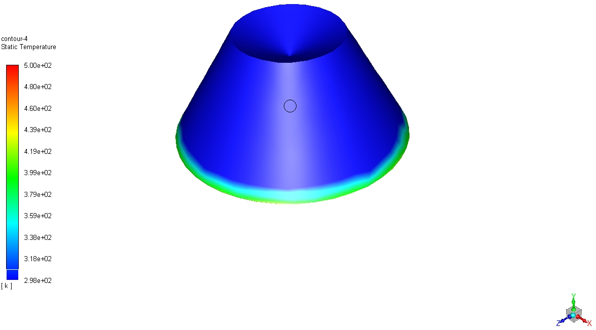
The contours (Figure 6, Figure 7, Figure 8 and Figure 9) show the characteristic thermal-front behaviour of a packed-bed storage system. Hot air enters the bed and progressively heats the upstream granite, while the downstream region remains comparatively cool during the transient charging period. The conical geometry produces a changing cross-sectional area, which modifies local flow distribution and therefore the spatial pattern of heat transfer. The thermal gradients demonstrate that the bed is not instantaneously at thermal equilibrium; rather, a moving thermal front controls the transient storage response.
3.3Heat-transfer-rate comparison
| Geometry | Particle size (mm) | Inlet T (K) | Outlet T (K) | Mass flow (kg/s) | Heat-transfer rate (kW) |
|---|---|---|---|---|---|
| Cube | 20 | 500 | 420 | 0.15 | 12.684 |
| Cube | 40 | 500 | 390 | 0.15 | 16.599 |
| Cylinder | 40 | 500 | 380 | 0.15 | 18.108 |
| Cone | 40 | 500 | 370 | 0.15 | 19.617 |
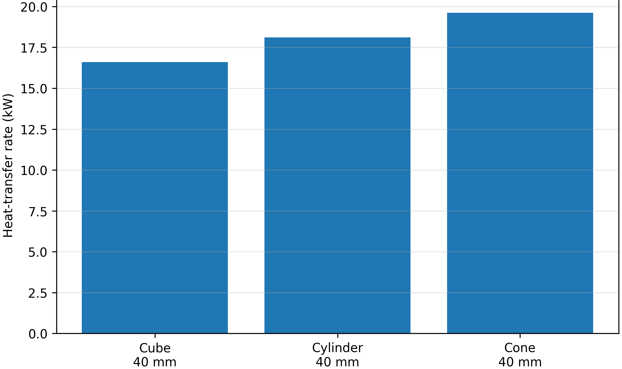
For the common 40 mm particle size (Table 2, Figure 10), the conical bed gives the highest reported heat-transfer rate (19.617 kW), followed by the cylindrical bed (18.108 kW) and the cubic bed (16.599 kW). Relative to the cube, the cylinder increases the reported heat-transfer rate by approximately 9.1%, while the cone increases it by approximately 18.2%. The outlet temperatures follow the same ordering: 390 K for the cube, 380 K for the cylinder and 370 K for the cone, under the conditions reported in the project.
3.4Pressure distribution and its relationship with thermal behaviour
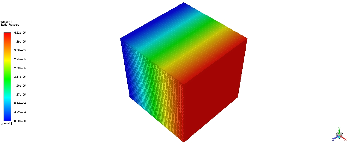
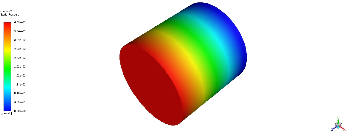
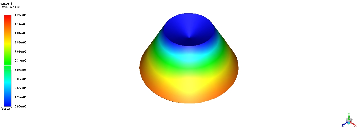
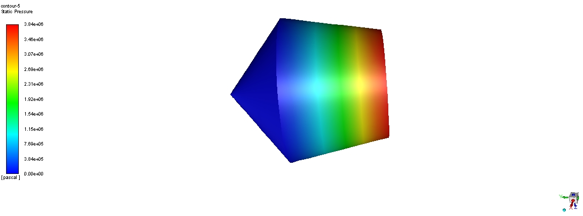
The pressure contours (Figure 11, Figure 12 and Figure 13) show progressive pressure loss along the flow direction. The project reports a relatively smooth pressure variation for the cylindrical case, while the changing cross-sectional area of the conical/frustum geometry produces a more non-uniform pressure field. This is important because thermal enhancement cannot be considered independently of hydraulic cost. A geometry that produces a larger heat-transfer rate may also modify velocity and pressure distributions.
3.5Outlet-temperature history
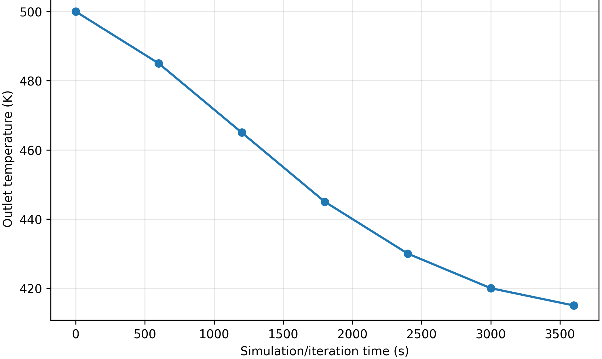
| Time (s) | Outlet temperature (K) |
|---|---|
| 0 | 500 |
| 600 | 485 |
| 1200 | 465 |
| 1800 | 445 |
| 2400 | 430 |
| 3000 | 420 |
| 3600 | 415 |
The project chart (Figure 14, Table 3) records a progressive reduction in outlet temperature from 500 K at the beginning of the plotted history to 415 K at 3600 s. This trend is consistent with the transient development of the thermal front and the increasing interaction between the hot air and initially cooler storage material.
3.6Interpretation in terms of packing structure
Packing structure affects thermal performance through the distribution of flow passages and solid surface area. A more tortuous arrangement can increase fluid–solid interaction and local mixing, but may also increase pressure loss. The geometry results from this project provide numerical evidence that changing the macroscopic bed shape changes the thermal response even when storage volume is held equal. However, the project did not produce a fully resolved quantitative orientation dataset for non-spherical particles. Therefore, the present paper does not claim a measured orientation effect. A rigorous orientation study should use non-spherical particles of equal volume because perfect spheres have no physically distinguishable orientation.
4Conclusions
- Equal-volume bed geometry significantly influences the thermal response of the investigated granite rockbed TES system.
- For 40 mm particles, the reported heat-transfer rates are 16.599 kW for the cube, 18.108 kW for the cylinder and 19.617 kW for the cone.
- The conical configuration produced the largest reported heat-transfer rate among the compared 40 mm cases.
- The temperature contours demonstrate a moving thermal front, with hot air progressively charging the upstream portion of the bed while cooler regions persist downstream.
- Outlet-temperature history confirms the transient nature of charging, with the reported outlet temperature decreasing from 500 K to 415 K over the plotted 3600 s period.
- Packing and geometry should be assessed jointly with pressure drop because thermal enhancement can be accompanied by additional hydraulic penalties.
- Particle orientation should be investigated separately with non-spherical, equal-volume particles if orientation is to form a defensible independent research variable.
5Contribution and future work
The paper's main contribution is the extraction of a geometry/packing-focused thermal comparison from the broader MSc study. It provides a numerical basis for comparing alternative equal-volume rockbed geometries and demonstrates how thermal fronts and heat-transfer rates respond to geometry changes.
Future work should resolve the actual particle-scale packing structures explicitly, compare ordered and random arrangements, and use non-spherical particles to quantify orientation effects. The next step should be a multi-objective optimisation in which heat-transfer rate, pressure drop and fan power are considered simultaneously.
References
- [1]Allen KG, von Backström TW, Kröger DG (2015). Rock bed pressure drop and heat transfer: Simple design correlations. Solar Energy, 115, 525–536.
- [2]Ergun S (1952). Fluid flow through packed columns. Chemical Engineering Progress, 48(2), 89–94.
- [3]Eppinger T, et al. (2021). Influence of wall structures on fluid flow and heat transfer in fixed beds. Processes, 9(4), 689.
- [4]Gautam A, et al. (2020). Experimental investigation of heat transfer and fluid-flow behavior of packed bed solar TES with porous spheres. Solar Energy, 204, 530–541.
- [5]Rabi’ AM, Radulovic J, Buick JM (2024). Packed bed thermal energy storage system: Parametric study. Thermo, 4(3), 295–314.
- [6]Schumann TEW (1929). Heat transfer: A liquid flowing through a porous prism. Journal of the Franklin Institute, 208, 405–416.
- [7]Wakao N, Kaguei S, Funazkri T (1979). Effect of fluid dispersion coefficients on particle-to-fluid heat transfer coefficients in packed beds. Chemical Engineering Science, 34, 325–336.