Water Engineering
Robust Design of a Riprap Basin Outlet
University of Ibadan, Ibadan, Nigeria
Published October 2026
Abstract
One of the major causes of hydraulic infrastructure deterioration is scour around the structure and culverts suffer from this at the outlet, resulting in partial or complete collapse of the structure, roadway damage, and increased maintenance costs. Conventional outlet protection systems are commonly designed with a single design discharge, usually the 25- or 50-year return period depending on the size of the channel bed. This gives little consideration to their performance under larger flood events and thus questions the possible effectiveness under long term use. This study presents a hydrological and hydraulic assessment of scour and the robust design of a riprap basin outlet protection system by considering multiple design discharges using a reinforced box culvert affected already by scour in Ibadan, Nigeria as a case study. A 37.4 km2 catchment area was determined from the area around the box culvert using HEC-HMS to estimate peak discharges corresponding to the 25-, 50-, and 100-year return periods. HY-8 was used to perform the hydraulic analysis of the box culvert using the city’s master plan design discharge and the aforementioned return periods, while scour characteristics were calculated in accordance with the Federal Highway Administration Hydraulic Engineering Circular No. 14 (FHWA HEC-14) procedures. A riprap basin and apron were designed using the city’s master plan discharge and its performance was assessed under higher return periods to determine its robustness and effectiveness under long term use. Results showed that under the design discharge, the proposed outlet protection provides adequate stability but there is a significant increase in riprap size and basin depth under the return periods. However, the basin width, length and apron length remained consistent for all discharges. The required median stone diameter increased progressively with increasing flood magnitude, showing that conventional single event design underestimates the protection required for scour prevention and channel preservation. A simplified robustness-based design framework is proposed to facilitate the assessment of riprap basin adequacy under multiple flood scenarios. The study demonstrates the importance of incorporating robustness assessment into culvert outlet protection design to improve infrastructure resilience and reduce scour-induced failures in urban drainage systems.
Keywords: box culvert; scour; riprap basin; hydraulic modelling; HEC-HMS; HY-8; outlet protection; robustness assessment
1Introduction
Urbanization and rapid land use changes have significantly altered natural hydrological processes by increasing impervious surfaces and modifying drainage pathways, resulting in greater runoff volumes, higher peak discharges, and increased hydraulic loading on stormwater infrastructure (Goudie, 2018; Goudie, 2022). Culverts are among the most commonly used hydraulic structures for conveying stormwater beneath transportation corridors while maintaining the continuity of natural waterways (Piotr et al., 2021). However, because culverts introduce artificial flow conditions into natural channels, they frequently generate high-velocity outlet flows capable of producing severe local scour, channel degradation, and bank erosion, thereby threatening the stability of both the drainage structure and adjoining road infrastructure (Ahmed et al., 2024b). The scour at culvert outlets has, therefore, emerged as one of the major causes of deterioration of hydraulic structures, which leads to expensive maintenance work, roadway failures and disruption of transportation systems.
The hydraulic response of the outlet flow of a culvert is controlled by the discharge, flow velocity, outlet geometry, tailwater conditions, channel slope, and bed material characteristics. When the confined flow reenters the natural channel, turbulence, hydraulic jumps and erosive vortices are produced, which increases the bed shear stress beyond the critical shear stress for sediment motion (Fantina, 2024; Oldenhof and Warmink, 2024). When the hydraulic forces applied exceed the resistance provided by the channel material, progressive scour begins downstream of the outlet, and the depth of scour is greatly dependent on discharge magnitude, flow duration, sediment characteristics and channel geometry (Ahmed et al., 2024; Karamigolbaghi et al., 2017).
Several outlet protection measures have been developed to mitigate these adverse hydraulic impacts, such as stilling basins, baffled aprons, impact basins, gabions, articulated concrete blocks, and riprap systems (Norman et al., 2012). Riprap basins are one of the most used energy dissipators among these options, thanks to their relatively low construction cost, ease of installation, flexibility to various field conditions, and satisfactory hydraulic performance (Yincan et al., 2017; Lyn et al., 2019). Riprap protection increases boundary roughness, facilitates the formation of hydraulic jump, decreases near-bed velocities, and decreases sediment entrainment downstream of the culvert outlet (Tyagi et al., 2016; Mohammadnezhad et al., 2026). The main factors that affect the hydraulic stability of a riprap basin include stone size, stone gradation, thickness of stone layer, basin geometry, and the size of design discharge (Rahimnejad and Ooi, 2016; Thompson and Kilgore, 2006).
Although riprap outlet protection has been widely adopted, the general approach to sizing riprap basins is based on a single design discharge, commonly the design storm that was used in the roadway planning process (Norman et al., 2012). This is sufficient to meet minimum hydraulic requirements for the selected design event, but will not give much information on the performance of the outlet protection during larger flood events. Climate induced extreme precipitation, increased rainfall variability, and rapid urban growth have led to more frequent exceedance of traditional design discharges, putting drainage infrastructure at risk of being exposed to hydraulic conditions well beyond those assumed in design. In such conditions, insufficient riprap size can cause its instability, particle displacement, formation of progressive scour, structural degradation, and high maintenance expenses (Jafarnejad et al., 2017; Mohammadnezhad et al., 2026).
In Nigeria, the design of culvert outlet protection is usually based on international hydraulic design manuals as local design methodologies are still limited. This means that outlet protection systems are seldom designed for more than the chosen design discharge, even though in the rapidly urbanising catchments, there is an increasing incidence of failures in infrastructure caused by flooding. Additionally, very little research has been done to assess the hydraulic adequacy of riprap basin designs systematically under various flood return periods that represent the local hydrology. This uncertainty will raise questions about the ability of the current outlet protection systems to withstand future hydraulic extremes and will point to the need for design procedures that can account for future extremes.
This study therefore presents a hydrological and hydraulic assessment of scour together with the robust design of a riprap basin outlet protection system for a reinforced box culvert located in Ibadan, Nigeria. Peak discharges corresponding to the 25-, 50-, and 100-year return periods were estimated using the Hydrologic Engineering Centre–Hydrologic Modelling System (HEC-HMS). Hydraulic performance of the culvert was subsequently analysed using HY-8, while scour characteristics and outlet protection requirements were evaluated using the Federal Highway Administration Hydraulic Engineering Circular No. 14 (FHWA HEC-14) procedures. A riprap basin and apron system was designed for the master plan discharge and subsequently assessed under higher flood magnitudes to determine its hydraulic robustness and identify the modifications required for improved resilience.
Unlike previous studies that focus primarily on the hydraulic design of outlet protection for a single discharge condition, the present study incorporates robustness assessment into the design process by evaluating riprap stability under multiple flood return periods. The proposed framework suggests a practical way to enhance the resilience of the culvert outlet protection systems and gives design guidelines relevant to urban drainage systems in Ibadan and catchments having similar hydrologic properties.
2Materials and method
2.1Description of the study area
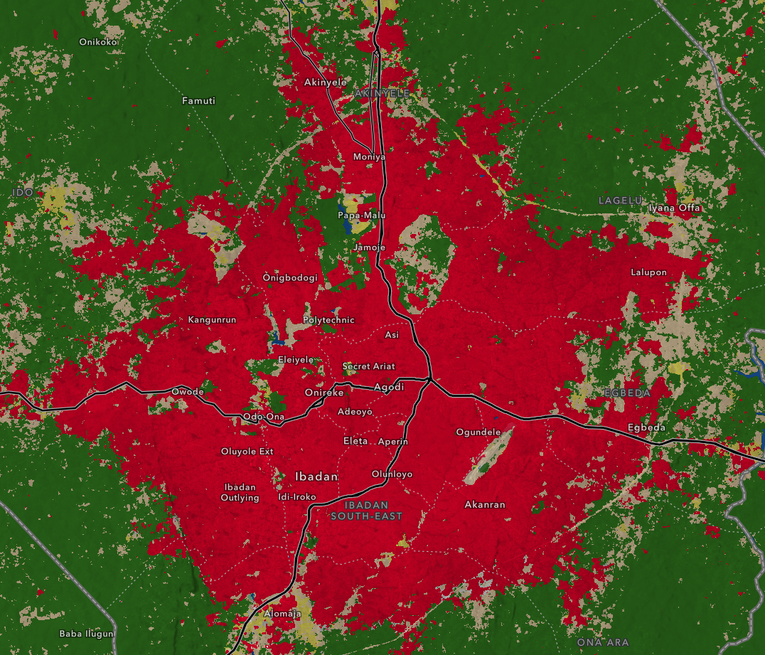
The study was carried out on a reinforced concrete box culvert situated in Ibadan, Oyo State, Nigeria. The culvert is part of an urban drainage network that carries storm runoff from an approximately 37.4 km² catchment area. The natural hydrological response has been modified by rapid urban development within the catchment, which has resulted in increased impervious surfaces, and consequently increased volumes of runoff and peak discharges during storm events. The culvert outlet is therefore exposed to high velocity flow conditions that can cause extensive local scour. The study area and its land cover classes are shown in Figure 1.
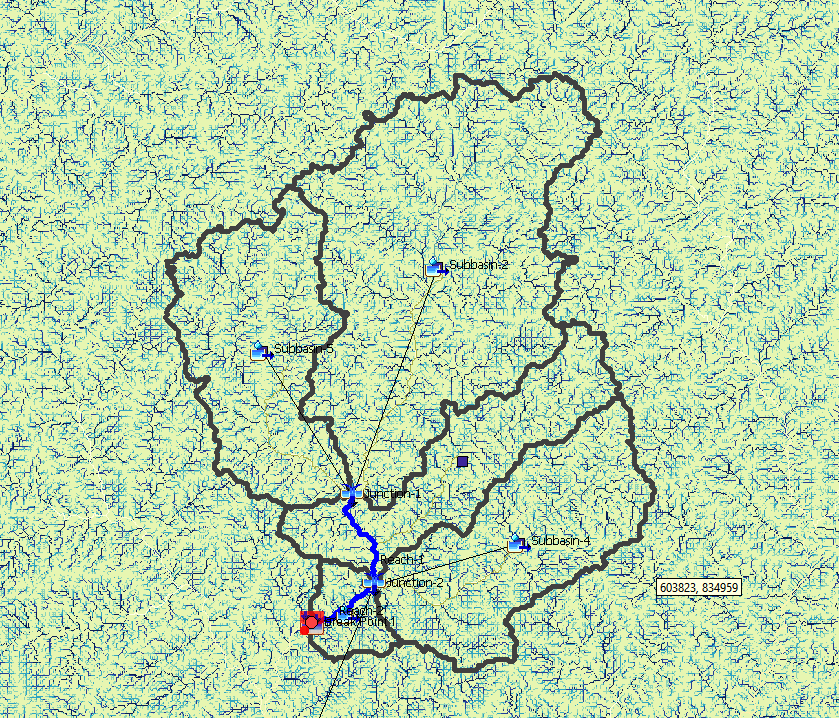
The characteristics of catchments needed for modelling the hydrology were obtained from digital elevation models, land use data, soil data, and available hydrological data. The data were analysed to develop watersheds, streams, sub-watersheds, and other hydrological parameters needed for runoff modelling. The subbasin characteristics are given in Table 1.
| Subbasin | Area (km2) | Curve number | Longest flowpath length (km) | Longest flowpath slope (m/m) | Time of concentration |
|---|---|---|---|---|---|
| Subbasin-1 | 16.218 | 80.4 | 2.0009 | 0.01872 | 4.53 |
| Subbasin-2 | 7.4355 | 77.5 | 9.04813 | 0.00809 | 3.32 |
| Subbasin-3 | 7.2802 | 79.5 | 7.08414 | 0.01186 | 3.22 |
| Subbasin-4 | 5.2337 | 80.2 | 6.34619 | 0.01157 | 3.63 |
| Subbasin-5 | 1.2225 | 81.4 | 6.52557 | 0.01068 | 1.03 |
| Total | 37.3899 |
2.2Hydrological modelling
Hydrological analysis was performed using the Hydrologic Engineering Center–Hydrologic Modeling System (HEC-HMS) to estimate peak discharges corresponding to the city master plan design flood together with the 25-, 50-, and 100-year return period storms. The hydrological model was developed from watershed characteristics derived from the processed spatial datasets. Basin losses were estimated using the Soil Conservation Service Curve Number (SCS-CN) method, while runoff transformation was performed using the SCS Unit Hydrograph. Channel routing was carried out using the Muskingum routing procedure where applicable.
The design rainfall depths were calculated using the Intensity-Duration-Frequency (IDF) relationship of Ibadan and then converted into hyetographs corresponding to the chosen return periods. Finally, the HEC-HMS model developed was run to obtain peak flows necessary for hydraulic computations. The catchment delineated from the DEM is shown in Figure 2.
Land cover and soil data were incorporated into the hydrological model to estimate the losses from rainfall and the generation of runoff. The land cover data was acquired from satellite-based land use maps from ESRI Sentinel-2 and soil information was classified based on the Hydrologic Soil Group (HSG) system. Both datasets were merged to create a Spatially Distributed Soil Conservation Service Curve Number (SCS-CN) grid for the study area. The SCS Curve Number method was used to calculate infiltration losses and the percentage of rainfall that infiltrates into the soil and the percentage that goes to direct surface runoff.
| Discharge | Total discharge (m3/s) |
|---|---|
| Design | 27.70 |
| 25-year | 66.61 |
| 50-year | 76.55 |
| 100-year | 87.39 |
2.3Hydraulic analysis of the culvert
The hydraulic performance of the reinforced box culvert was analyzed using HY-8 software, which is a product of the United States Federal Highway Administration (FHWA). The parameters such as culvert geometry, inlet shape, road alignment, Manning’s n value, invert elevations, and tail water condition were provided to the software for hydraulic analysis.
This analysis was done separately for each design discharge calculated using the HEC-HMS model. Hydraulic parameters, such as the outlet velocity, headwater depth, tail water depth, flow regime, hydraulic grade line, and road flooding condition were determined during the process. The focus was on the outlet velocity due to its effect on the scouring process.
2.4Scour assessment
Predictions of scour depth downstream of the culvert outlet were done according to the methods prescribed in FHWA HEC-14 using HY-8. Estimations of the dimensions of the predicted scour hole were carried out based on the design discharge using the empirical formulas for riprap basin design.
The predictions of scour were based on the hydraulic parameters such as outlet velocity, hydraulic radius, discharge, tailwater depth, and sediment properties (D16 and D84). Scour depth, scour width, scour length, and scour volume were predicted to determine the severity of erosion for each flood scenario.
Scour depth of 1.1 m at the culvert outlet was obtained from field investigations. This observed depth was considerably lower than the HEC-14 predicted scour depth of 3.369 m for the master plan design discharge, representing a difference of over 300%.
Several factors contribute to this discrepancy between the empirical prediction and field observation including rainfall input data, limited topographic data, the conservative nature of HEC-14, flood history and temporal effects.
2.5Riprap basin design
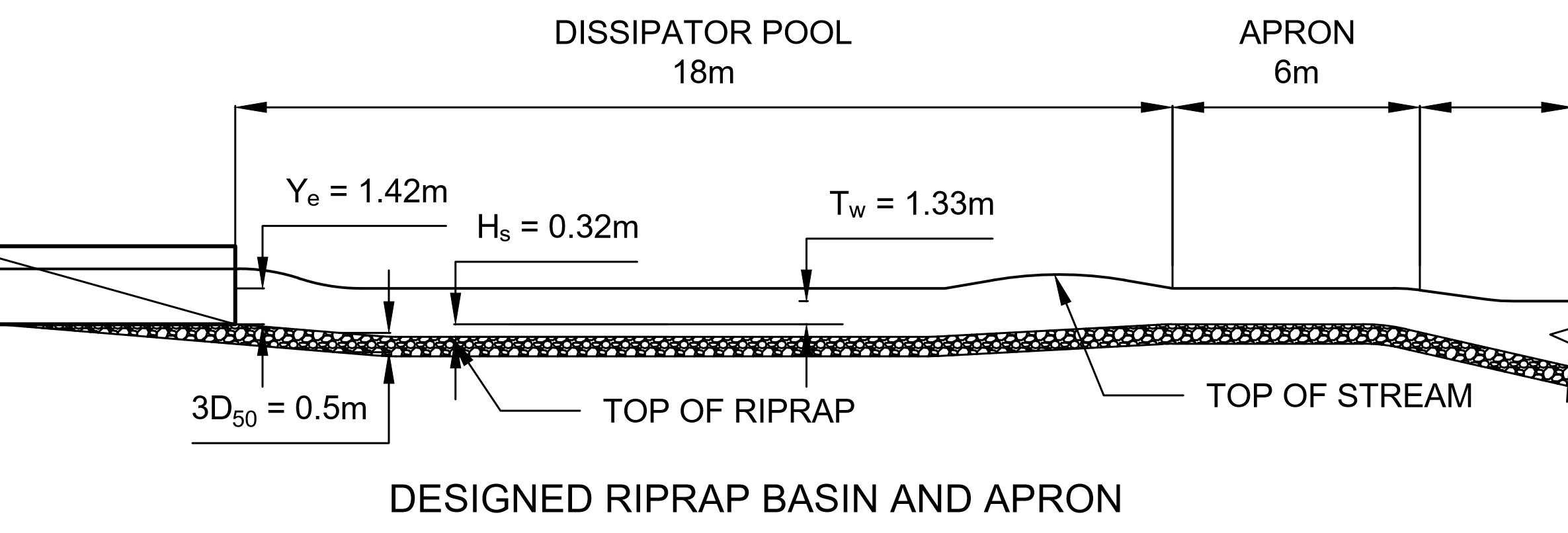
The designed energy dissipator for the reinforced box culvert was a riprap basin developed using HY-8 riprap basin procedures for a design discharge of 27.70 m³/s. The culvert has a clear width of 6.0 m and a height of 2.0 m, with an outlet depth of 1.42 m, outlet velocity of 3.24 m/s, and a Froude number of 0.73. The tailwater depth at the downstream end was 1.33 m, indicating that the outlet flow was controlled by downstream conditions.
For the riprap mixture, a median stone size of D50 = 0.160 m and a maximum stone size of Dmax = 0.200 m were selected. The resulting riprap basin met the stability checks of the design procedure, Hs/D50 = 2.002, which is greater than the criterion of Hs/D50 > 2.0. The ratio D50/Ye was also within the acceptable range of 0.1 to 0.7 (D50/Ye = 0.120). The final basin geometry from the design is: basin length = 24.0 m, basin width = 22.0 m, apron length = 6.0 m and pool length = 18.0 m. The riprap thickness and depth of pool is 0.320 m and is the depth of the basin.
2.6Robustness assessment
In order to verify the reliability of the proposed solution for the outlet protection, the riprap basin was analyzed with regard to the hydraulic characteristics associated with the 25-year, 50-year, and 100-year flood events. For each flood event, the median stone size, basin dimensions, and stability criteria were re-calculated and compared to the initial design for the master plan discharge. The results are compared in Table 3.
| Event | Discharge, Q (m3/s) | Brink velocity, Vo (m/s) | Pool depth (m) | Required D50 (m) | Pool length (m) | Apron length (m) | Basin width (m) |
|---|---|---|---|---|---|---|---|
| Design | 27.7 | 3.46 | 0.32 | 0.16 | 18 | 6 | 22 |
| 25-year | 66.61 | 5.061 | 0.63 | 0.315 | 18 | 6 | 22 |
| 50-year | 76.55 | 5.365 | 0.719 | 0.34 | 18 | 6 | 22 |
| 100-year | 87.39 | 5.645 | 0.743 | 0.37 | 18 | 6 | 22 |
The increase in riprap size needed under each return period was then determined in order to assess the robustness of the design as well as the upgrading that is needed in order to achieve adequate performance during an extreme flood event.
This robustness analysis served as the foundation for the evaluation of the stability of a conventionally designed riprap basin under an extreme flood event.
3Results and discussion
3.1Hydrological analysis
A HEC-HMS simulation successfully created hydrographs of the chosen design floods, making it possible to estimate the peak discharges for the city master plan design flood and 25-, 50-, and 100-year return periods. The peak discharge in the case of the city master plan design flood is 27.70 m³/s. At the same time, the peak discharges for 25-, 50-, and 100-year return periods are 66.61 m³/s, 76.55 m³/s, and 87.39 m³/s, correspondingly (Table 2). This demonstrates the significant increase in runoff volume depending on the return period of a storm and makes it important to take into account extreme hydrological conditions when designing culvert outlet protection.
The increasing trend of discharge demonstrates the logical correlation between return period of rainfall and runoff. Higher design floods created larger discharges, which means that an outlet protection designed for the master plan discharge will have to withstand much higher hydraulic loads.
3.2Hydraulic performance of the culvert
The hydraulic analysis conducted through HY-8 indicated that the reinforced box culvert was able to convey the master plan discharge design without overtopping. Nonetheless, the performance of the culvert with regard to hydraulics declined with an increase in discharge levels. It was also observed from the analysis that overtopping starts taking place from a flow level of about 52.40 m³/s, which means that any flood level beyond this level would not be conveyed through the culvert barrel. The results are given in Table 4.
| Discharge | Total discharge (m3/s) | Culvert discharge (m3/s) | Normal depth (m) | Critical depth (m) | Outlet depth (m) | Tailwater depth (m) | Outlet velocity (m/s) | Tailwater velocity (m/s) |
|---|---|---|---|---|---|---|---|---|
| Design | 27.70 | 27.70 | 1.13 | 1.29 | 1.42 | 1.33 | 3.24 | 2.15 |
| 25-year | 66.61 | 60.73 | 2.00 | 2.00 | 2.00 | 2.14 | 5.06 | 2.77 |
| 50-year | 76.55 | 64.38 | 2.00 | 2.00 | 2.00 | 2.30 | 5.36 | 2.87 |
| 100-year | 87.39 | 67.74 | 2.00 | 2.00 | 2.00 | 2.46 | 5.64 | 2.98 |
From the results obtained from the study of hydraulics, it is clear that the velocity at the outlet is increased with the increase in discharge until the overtopping takes place. As a result, the flood water passes around the culvert. This fact indicates the need to take into account the hydraulic control regime while designing outlet protection.
3.3Scour prediction
Results obtained from FHWA HEC-14 guidelines indicated considerable scouring taking place at the culvert outlet under all design situations. Scouring depth ranged from 3.37 m under master plan discharge to 4.78 m under 100-year flood flow, whereas scouring width, scouring length, and scouring volume increased with increasing flows. This shows that flow discharge plays a key role in scouring intensity. The predicted scour dimensions are given in Table 5.
The observed increased size of the scour is due to the higher velocity and high flow energy of the larger floods. High hydraulic loads will lead to increased sediment removal, resulting in the gradual increase in the size of the scour hole. Previous studies have also documented similar findings, where flow discharge was found to be one of the key parameters that control local scour formation at culvert outlet points (Ahmed et al., 2024; Oldenhof and Warmink, 2024).
3.4Riprap basin design
The riprap basin was designed based on the city master plan discharge in line with the FHWA HEC-14 design procedure. The final design parameters include a median size of riprap (D50) of 0.160 m, a riprap depth of 0.320 m, a basin length of 24.0 m, and a basin width of 22.0 m. This satisfies the hydraulic stability criteria for the design discharge used. The basin is shown in Figure 3.
The design of the basin allows for spread of flow and the creation of a hydraulic jump which slows the velocity of the outlet and decreases the bed shear stress on the downstream channel. The thickness of riprap selected also meets the minimum thickness required for outlet protection as recommended by FHWA HEC-14.
3.5Robustness assessment
A performance evaluation of the proposed riprap basin was conducted for the 25-, 50- and 100-year flood events to assess the robustness. The results show that the basin is stable for the master plan discharge, but as the flood magnitude increases, the size of the riprap needs to increase. The required median stone diameter was increased by about 97%, 113% and 131% for the 25-, 50- and 100-year return periods, respectively, compared to the original design.
The significant rise in the required stone size clearly indicates that the traditional outlet protection based on a single discharge can be unstable during the extreme flood events. Larger floods generate higher hydraulic forces on the riprap layer, which can lead to higher likelihood of riprap displacement and channel bed exposure to erosion. Therefore, using a single design discharge can underestimate the level of protection needed to achieve long-term infrastructure resilience.
3.6Engineering implications
The results show that a good hydraulic design should not only consider the traditional single event design, but should also consider outlet protection under multiple return periods. Such an approach enables engineers to identify the limits of a proposed design and determine whether additional riprap size, basin dimensions, or other modifications are necessary to ensure satisfactory performance during extreme flood events. The proposed framework is shown in Figure 4.
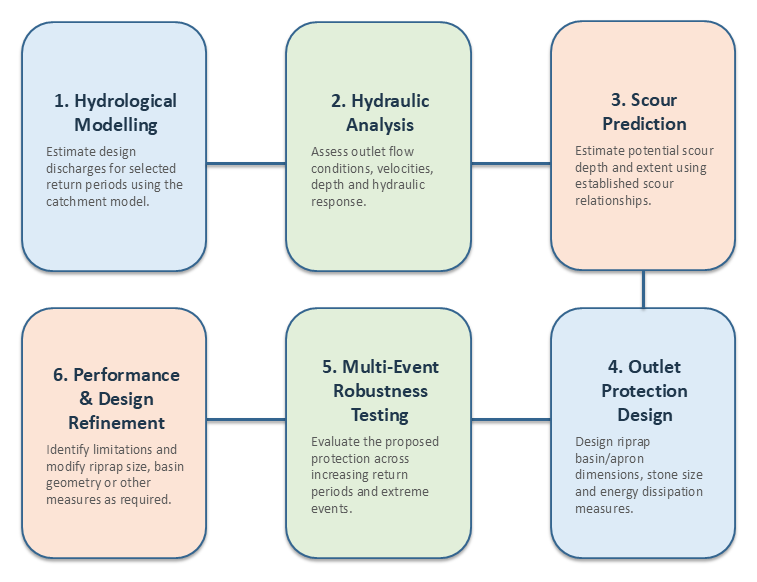
The proposed methodology provides a practical design framework for reinforced box culvert outlet protection in Ibadan and similar urban catchments. By integrating hydrological modelling, hydraulic analysis, scour prediction, riprap basin design, and robustness evaluation into a unified workflow, the approach offers improved confidence in outlet protection performance under future hydraulic extremes. The methodology also supports more resilient drainage infrastructure capable of reducing maintenance requirements and minimizing scour-induced structural failures.
4Conclusion
This study presented a hydrological and hydraulic assessment of scour together with the robust design of a riprap basin outlet protection system for a reinforced concrete box culvert located in Ibadan, Nigeria. Peak discharges corresponding to the city master plan design flood and the 25-, 50-, and 100-year return periods were successfully estimated using HEC-HMS, while the hydraulic performance of the culvert was evaluated using HY-8. Scour characteristics and outlet protection requirements were subsequently determined using the FHWA Hydraulic Engineering Circular No. 14 (HEC-14) design procedures.
The hydrological analysis showed an increasing trend in peak discharge with increasing return period, which in turn led to greater hydraulic loading on the culvert outlet. Hydraulic simulations also indicated that the culvert is capable of conveying the master plan design discharge, but will overtop the roadway under higher inflow conditions. Similarly, scour predictions showed that as discharge increased, the scour depth and extent increased significantly, highlighting the strong influence of flood magnitude on downstream channel stability. The master plan discharge outlet in the riprap basin was found to be adequately protected under the design flood condition, but the robustness assessment revealed that the median stone size of the riprap basin would need to be increased significantly to allow the basin to remain hydraulically stable during the 25-, 50- and 100-year return period floods.
The findings show that the traditional outlet protection based on a single outlet design flow may not be adequate for more extreme flood events. By integrating the robustness assessment into the design process, engineers can assess the performance of the riprap protection for a variety of hydraulic loading scenarios and determine the necessary changes to increase the infrastructure's long-term reliability. The proposed framework offers a practical and systematic solution to improve the design of culvert outlet protection systems in fast urbanizing catchments.
Future culvert outlet protection designs should include robustness evaluation along with the traditional hydraulic design process. Future research should also include physical laboratory experiments and computational fluid dynamics (CFD) simulations to further test and validate the proposed methodology and to optimize riprap basin configurations under different hydraulic and sediment transport conditions to create a partially grouted riprap system.
References
- [1]Ahmed KO, Kavianpour MR, Amini A, Aminpour Y (2024a). Numerical modelling of downstream scour in circular culverts: Impact of inlet blockages and variable flow conditions. PLoS ONE, 19(10), 1–25. https://doi.org/10.1371/journal.pone.0312501
- [2]Ahmed KO, Kavianpour MR, Amini A, Aminpour Y (2024b). Physical modeling of the effect of shape, blockage, and flow variability on scour in culvert outlets. Plos One, 19(6 June). https://doi.org/10.1371/journal.pone.0306252
- [3]Merry MA (2017). Experimental study for determining Manning’s coefficient with different slopes and channel bed materials. Kufa Journal of Engineering, 8(3), 76–88. https://doi.org/10.30572/2018/kje/8031160
- [4]Karamigolbaghi M, Ghaneeizad SM, Atkinson JF, Bennett SJ, Wells RR (2017). Critical assessment of jet erosion test methodologies for cohesive soil and sediment. Geomorphology, 295, 529–536. https://doi.org/10.1016/j.geomorph.2017.08.005
- [5]Nguyen DP, Hoang NB, Tran HT, Indra P, Pham BT (2024). Impact of roughness elements on reducing flow velocity at outlets of box culverts. Magazine of Civil Engineering, 17(1). https://doi.org/10.34910/MCE.125.3
- [6]Norman JM, Houghtalen RJ, Johnston WJ (2012). Hydraulic design of highway culverts (Hydraulic Design Series No. 5). Federal Highway Administration.
- [7]Oldenhof M, Warmink DJJ (2024). Understanding the development and behaviour of scour holes in fluvial lowland rivers: Literature report.
- [8]Rahimnejad R, Ooi PSK (2016). Factors Affecting Critical Shear Stress of Scour of Cohesive Soil Beds. Transportation Research Record, 2578(1), 72–80. https://doi.org/10.3141/2578-08
- [9]Szpakowski W (2014). Outlet flow velocity in circular culvert. Archives of Hydroengineering and Environmental Mechanics, 61(3–4), 193–203. https://doi.org/10.1515/heem-2015-0013
- [10]Ross CW, Prihodko L, Anchang JY, Kumar SS, Ji W, Hanan NP (2018). Global Hydrologic Soil Groups (HYSOGs250m) for Curve Number-Based Runoff Modeling (Version 1). ORNL Distributed Active Archive Center. https://doi.org/10.3334/ORNLDAAC/1566 Date Accessed: 2026–07–04
- [11]Kilgore RT, Cotton GK, Robinson KM, Schall JD (2006). Hydraulic design of energy dissipators for culverts and channels (Hydraulic Engineering Circular No. 14, 3rd ed., FHWA-NHI-06-086). Federal Highway Administration, U.S. Department of Transportation.
- [12]Assessment of Implementing Land Use/Land Cover LULC 2020-ESRI Global Maps in 2D Flood Modeling Application - Scientific Figure on ResearchGate. Available from: https://www.researchgate.net/figure/LULC-2020-ESRI-base-Mannings-roughness-values-using-both-average-and-weighted-average_fig8_366024442 [accessed 18 Jul 2026]
- [13]Goudie AS (2018). The Human Impact on the Natural Environment: Past, Present, and Future (8th ed.). Wiley-Blackwell.
- [14]Goudie AS (2022). Urban Geomorphology: Landforms and Processes in Cities. Elsevier.
- [15]Lyn DA, Cooper CM, Liu X (2019). Evaluation of Riprap Design Criteria for Highway Bridge Pier and Abutment Protection. Indiana Department of Transportation / Purdue University.
- [16]Mohammadnezhad H, Mohammadi M, Ghaderi A (2026). Riprap mitigation of downstream scour at grade-control structures. Scientific Reports, 16(1), Article 2481.
- [17]Tyagi A, Brown J, Al-Madhhachi A (2016). Laboratory modeling of energy dissipation and outlet protection for culverts. Journal of Hydraulic Engineering, 142(8), 04016021.
- [18]Yincan Y, Sheng Q, Zhen L (2017). Local Scour and Protection of Marine Structures and Hydraulic Outlets. Springer.