Industrial IoT
Arduino Uno Based Smart Obstacle Detection and Collision Avoidance System for Vehicles
Department of Computer Science (IoT and Cybersecurity including Blockchain), Alva’s Institute of Engineering and Technology, Moodbidri, Karnataka, India
Published October 2026
Abstract
Road accidents often happen because the driver reacts late or simply does not see the obstacle, and the radar and LiDAR systems that could help are too expensive for small vehicles or low-budget projects. In this paper we describe the design of a cheap embedded obstacle detection and collision avoidance system built on an Arduino Uno. An HC-SR04 ultrasonic sensor sits on an SG90 servo at the front of the chassis and sweeps the area ahead. The Arduino turns the echo time into a distance, smooths the readings and sorts the situation into a safe, warning or stop zone. In the warning zone a buzzer and a 16×2 LCD alert the driver and the motors slow down as the gap shrinks. In the stop zone the L298N driver brakes the motors, the servo scans for a clear direction, and the car either steers around the obstacle or stays put. We looked at five published prototypes (ultrasonic braking, Li-Fi assisted following, GPS-assisted braking distance, multi-sensor avoidance and accident identification), compared what they report, and used them to choose our design. A simple stopping-distance calculation shows that the roughly 4 m range of the HC-SR04 limits the speed at which such a system can work, and we also set out a test plan for the prototype.
Keywords: Arduino Uno; HC-SR04; ultrasonic sensor; obstacle detection; collision avoidance; servo scanning; L298N; embedded systems
1Introduction
Road crashes are one of the main causes of death worldwide, and the WHO’s 2018 status report counts about 1.35 million road deaths a year [6]. Earlier papers quote similar figures: Aliyu et al. give roughly 1.2 million deaths a year, mostly in low- and middle-income countries [2], and Krishnan 1.25 million people affected annually [3]. Most of these crashes could have been predicted and prevented [2]. A driver may not notice an obstacle in time, and an ordinary brake works only after the driver has seen the hazard and reacted, which adds delay [2]. Forward collisions in particular often come from small mistakes such as keeping too little distance to the car ahead [4].
Collision avoidance features try to close this gap by watching the road and either warning the driver or acting for them. They are mostly found in expensive vehicles [2], and the sensors behind them (radar, LiDAR and cameras [4]) add cost, processing load and calibration work. Ultrasonic ranging is far cheaper. Unlike infrared sensors, it is not upset by sunlight or by dark-coloured targets [2], and it connects easily to a microcontroller. The downside is its short range and its sensitivity to the target surface [4]. Krishnan [3] also points out that ultrasonic sensing is accepted in industry while LiDAR is held back by cost, and quotes an accuracy of ±0.05 m for ultrasonic sensors against ±0.3 m for LiDAR.
This paper describes an Arduino Uno based obstacle detection and collision avoidance system with one HC-SR04 sensor mounted on a servo. Our main points are:
- a modular hardware and software design that combines angular scanning with a graded response (alert, slowing, braking and steering) on a low-cost 8-bit board;
- a comparison of five published microcontroller-based prototypes, which we used to choose our design parameters and test methods;
- a stopping-distance calculation showing how far the HC-SR04 range limits the speed of an ultrasonic-only system; and
- a test plan covering ranging error, response time, stopping distance and avoidance success, so that the prototype can later be compared with the reviewed work.
The rest of the paper is organised as follows. Section 2 reviews related work and Section 3 states the problem and objectives. Sections 4 and 5 describe the architecture and working principle, Section 6 the software, and Section 7 the evaluation plan. We then discuss the design, its limitations and future scope, and conclude.
2Related work
Five prototypes form the basis of this work; Table 1 summarises them.
Mahamud et al. [1] built an accident prevention and identification unit on an Arduino Uno with a 10-DOF IMU accelerometer, a GPS receiver and a SIM900A GSM module. The measured speed is checked against a limit set for each road segment, and if it is exceeded an LCD and an audio module warn the people in the car. When the tilt reading suggests an accident, an SMS with the GPS coordinates is sent. The authors admit that the speed limits and coordinate ranges have to be entered beforehand. The system does not look for obstacles ahead, so it complements range-based avoidance instead of replacing it.
Aliyu et al. [2] designed a crash avoidance system around an ATmega328P Arduino with HC-SR04 sensors at the front and rear. They simulated it in MapleSim first and then built a prototype. A red LED lights when an object is detected, the buzzer starts at 3 m, and precautionary braking engages at 2 m. In ten tests with a 30 cm set distance the distance error was 12.8 %, and the time from alarm to stop averaged 0.86 s.
Krishnan [3] paired an HC-SR04 sensor with Li-Fi communication between vehicles. The leading car measures the gap and shows “WARNING” or “SAFE ZONE” against a 1 m threshold. It also converts the distance into a target speed with a linear rule and sends that speed by visible light to the car behind. The sensor worked over 10–100 cm in the prototype. The author notes that Li-Fi needs a line of sight and suffers from white-light interference, and that the safety margin is limited by the sensor range.
Gunawan et al. [4] built a prototype on an RC car with an Arduino Uno, an HC-SR04 sensor and a GPS receiver. The measured gap and the GPS speed go into a time-to-collision based algorithm that estimates a safe braking distance. A buzzer and LED warn the driver, and a micro servo closes the window and tightens the seat belt as a precaution. Ranging error grew with distance, from 0.8 % at 40 cm to 30.7 % at 100 cm. The sensor did better on a smooth walkway than on rough pavement, and GPS noise near buildings hurt the speed estimate.
Xiao [5] built a tracked car on an ESP8266 board with three HC-SR04 sensors (front, left and right) and a sound sensor. The three-bit pattern of which sensors see an obstacle selects one of five stop, turn or reverse strategies, and a phone can take over manually through Wi-Fi. Each situation was tested 100 times and the success rate ranged from 89 % to 100 %.
| Ref. | Platform and sensing | System action | Reported outcome / limitation |
|---|---|---|---|
| [1] | Arduino Uno; IMU accelerometer, GPS, SIM900A GSM | Overspeed and tilt warning (LCD, audio); SMS with coordinates | Works with predefined limits and coordinates; no obstacle sensing |
| [2] | Arduino (ATmega328P); front and rear HC-SR04 | LED, buzzer, LCD warning; automatic braking | 12.8 % distance error; 0.86 s average response (10 trials) |
| [3] | Arduino Uno; HC-SR04; Li-Fi V2V link | Gap-to-speed command sent to following car; LCD status | 10–100 cm sensing; 1 m margin; line-of-sight Li-Fi |
| [4] | Arduino Uno; HC-SR04; GPS; RC car | Braking-distance based buzzer/LED; window and belt servo | Error 0.8–30.7 % over 20–100 cm; degraded on rough surface |
| [5] | ESP8266 board; 3 × HC-SR04; sound sensor | Five stop/turn/reverse strategies; Wi-Fi manual mode | Success 89–100 % (100 trials per case) |
| This work | Arduino Uno; 1 × HC-SR04 on servo (0–180°) | Buzzer and LCD alert; proportional slowing; braking; scan and steer | To be measured (Table VI) |
Broader surveys look at collision avoidance at a much higher level. Dahl et al. review the threat-assessment methods used to decide when a collision is imminent, from simple threat metrics to optimisation, probabilistic and machine-learning approaches [7]. Fu et al. survey data-driven collision avoidance that combines sensing, vehicular communication and artificial intelligence [8]. Our system sits at the simple, low-cost end of this range.
Looking at the five prototypes, a few things stand out. Four of them use an HC-SR04-type sensor to measure the gap, so a cheap ultrasonic front end is clearly workable. The accuracy of that sensor depends on the distance and the surface [4], so it makes sense to average several readings and calibrate instead of trusting one echo. And the systems that do more than warn need either extra hardware (GPS, Li-Fi, Wi-Fi) or several fixed sensors [5]. We take a different route: one sensor on a servo gives both forward monitoring and an angular scan, and the response is graded between warning and full stop using a distance-to-speed rule like the one in [3].
3Problem statement and objectives
We need a cheap, reliable, real-time obstacle detection system that spots hazards early enough for the driver to respond or for the vehicle to avoid the collision itself. Five challenges follow from this: (i) detecting obstacles accurately at short range in real time; (ii) reducing missed detections caused by the shape, size or angle of the target; (iii) warning the driver immediately; (iv) slowing or stopping the vehicle reliably; and (v) keeping the solution compact and cheap enough to fit into a vehicle. Our objectives are to:
- 1. design a low-cost embedded obstacle detection system;
- 2. obtain real-time distance measurement with the HC-SR04;
- 3. give instant driver alerts through a buzzer and an LCD;
- 4. reduce speed or stop automatically on detection; and
- 5. build a scalable, affordable prototype for vehicle integration.
4System architecture
4.1Overview
The system has three connected modules: sensing, processing and actuation (Figure 1). The HC-SR04 is fixed on an SG90 servo at the front of the chassis so it can turn through 0–180°. The Arduino Uno triggers the sensor, measures the echo, decides what to do and drives the outputs. Keeping the modules separate makes each one easy to test on its own, and lets us swap parts later, for example the sensor, without redesigning everything.
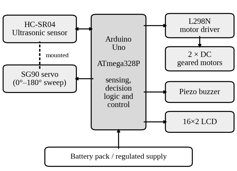
4.2Hardware modules
Arduino Uno. The Uno uses the ATmega328P, an 8-bit AVR microcontroller running at 16 MHz. It has 14 digital I/O pins, six analogue inputs, 2 KB of SRAM and 1 KB of EEPROM, and works at 5 V with a 7–12 V supply input [2], [4]. Six of its pins can give PWM output for speed control [2]. It runs the sensing, filtering and decision logic.
HC-SR04 ultrasonic sensor. After a 10 µs trigger pulse the module sends out eight 40 kHz pulses, and it returns an echo pulse whose width is proportional to the distance [4], [5]. It runs from 5 V and measures from a few centimetres up to about 400 cm [2], [4]. The manufacturer’s datasheet [9] specifies a 2 cm to 4 m range, a 15° measuring angle, and a measurement cycle of more than 60 ms; it also asks for a fairly smooth target of at least 0.5 m².
SG90 servo. This is a 9 g micro servo that runs on 5 V and turns through 180° [4]. It rotates the sensor so that we can build a rough picture of the obstacles ahead of the vehicle.
L298N motor driver and DC motors. The L298N is a dual full-bridge driver that accepts standard TTL logic levels, has two enable inputs to switch each bridge independently of the direction inputs, and can carry a total DC current of up to 4 A [10]. In our design it sets the direction of two geared DC motors and, through PWM on its enable inputs, their speed. Reference [5] uses the same idea of PWM speed control with direction pins for steering.
Buzzer and LCD. A piezo buzzer gives the audible alert, and a 16×2 character LCD shows the alert state and the measured distance, much like the warning units in [2] and [3].
Power. A battery pack feeds a regulated 5 V rail for the logic, sensor, servo and display. The motors should run from a separate supply with a common ground, so that current surges from the motors and servo do not disturb the logic.
4.3Pin assignment
Table 2 lists the proposed connections. The motor-speed lines use PWM pins on a different timer from the Servo library, and the LCD runs in 4-bit mode on the analogue pins.
| Module | Uno pins | Function |
|---|---|---|
| HC-SR04 | D7, D8 | Trig (output), Echo (input) |
| SG90 servo | D9 | Signal (Servo library) |
| L298N | D5, D6 | ENA, ENB (PWM speed) |
| L298N | D2, D4, D12, D13 | IN1–IN4 (direction) |
| Buzzer | D3 | Tone output |
| 16×2 LCD | A0–A5 | RS, E, D4–D7 (4-bit) |
4.4Drive logic
Each L298N channel has an enable input, which we use for PWM speed control, and two direction inputs [10]. With enable high, opposite levels on the two inputs run the motor forwards or backwards and equal levels brake it; with enable low the motor coasts. Table 3 lists the resulting vehicle motions. Which level means forward depends on how the motors are wired, as also noted in [5].
| Motion | Left motor | Right motor |
|---|---|---|
| Advance | Forward | Forward |
| Reverse | Backward | Backward |
| Turn left | Stop or backward | Forward |
| Turn right | Forward | Stop or backward |
| Stop | Brake | Brake |
5Working principle and methodology
5.1Distance measurement
Distance comes from the round-trip time t of the ultrasonic burst and the speed of sound vs [2], [5]:
Dividing by two accounts for the trip out and back. The speed of sound depends on the air temperature T (°C) [2]:
At 20 °C this gives 343.5 m/s, so d (cm) ≈ t (µs)/58, the same conversion used in [5]. If the assumed temperature is wrong by 10 °C, vs changes by 6 m/s, about 1.7 %. A fixed 343 m/s is therefore good enough for indoor tests, and a temperature reading can be added for wider conditions. The vehicle’s own movement during the echo time can be ignored because sound is much faster than the vehicle [5].
5.2Filtering and validation
We do not trust a single echo. Reference [4] saw readings fluctuate with the surface and found that averaging improved the agreement between distance and braking estimates. In each control cycle we therefore take n readings, drop zero (no-echo) values and use the median as D. A warning or stop is raised only if m cycles in a row fall below the threshold, which suppresses one-off false triggers. We will set n and m during calibration. Pings are spaced by at least 60 ms, as the datasheet recommends [9], so that echoes from the previous ping die out. The longest echo, from a target at 4 m, returns after 2 × 4 / 343.5 ≈ 23 ms, so this spacing leaves a comfortable margin.
Filtering costs time. If Tp is the ping spacing and tact the delay of the motor and buzzer actuation, the detection-to-action latency is roughly
so every extra sample or confirmation cycle adds about 60 ms to tr. This has to be balanced against the stopping-distance requirement in Section 5.5.
5.3Zone-based decision and speed law
Two distance thresholds split the space ahead into three zones (Figure 2, Table 4): a warning distance dw and a stop distance ds, with ds < dw. A third parameter, the clearance dc, is the smallest gap the vehicle needs before it will steer into a scanned direction. Reference [2] warns at 3 m and brakes at 2 m, and [3] uses a single 1 m threshold. We leave the values as parameters because the speed and braking behaviour of our prototype are not yet known.
| Zone | Condition | Response |
|---|---|---|
| Safe | D ≥ dw | Full speed; alarms off; LCD shows distance |
| Warning | ds < D < dw | Intermittent buzzer; LCD alert; motor duty reduced with D |
| Stop | D ≤ ds | Motors braked; continuous buzzer; LCD alert; scan and steer |
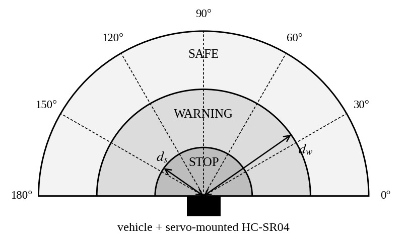
In the warning zone the PWM duty u falls linearly with the remaining gap, in the same way that [3] maps distance to a commanded speed:
where umax is the cruising duty and umin is the smallest duty that still turns the wheels, which we find by experiment. At D ≤ ds the motors are braked by putting both inputs of each L298N channel at the same level.
5.4Angular scan and heading selection
After a stop, the servo sweeps from 0° to 180° in steps of Δθ and measures the distance Dk at each angle θk, waiting for the servo to settle before every ping. The beam of the module is narrow (a 15° measuring angle according to the datasheet [9]), so Δθ should be no larger than that, otherwise some sectors would be missed. With Δθ = 15° the sweep has 13 positions, so at 60 ms per ping a full scan takes roughly 0.8 s plus the servo settling time. The preferred heading is
with ties resolved towards 90° to keep the turn small. If no direction has enough clearance, the vehicle stays stopped with the alarm on. This extends the front/left/right classification of [5] to K+1 angles using a single sensor, at the price of a scan time during which the vehicle is stationary. Turning is open-loop and timed, and we calibrate the turn duration on the chassis.
5.5Stopping-distance consideration
For the response to prevent contact, the stop distance ds must be at least the distance the vehicle travels before it halts. With speed v, system latency tr and constant deceleration a, the kinematic relation used in [3] (v2 − u2 = 2as) gives:
The sensor cannot see beyond dmax ≈ 4 m, so the highest speed from which the vehicle can still be stopped inside the sensing range follows from setting the right side equal to dmax:
With the maximum deceleration of 9 m/s² quoted in [3] for a car with ABS and dmax = 4 m, Eq. (7) gives about 30.5 km/h if latency is ignored, and about 13.5 km/h with the 0.86 s response time reported in [2] (Figure 3). These are optimistic upper bounds, since they assume the obstacle is picked up right at the edge of the range and that braking is ideal. They still show why an ultrasonic-only system suits low-speed vehicles and prototypes, and why longer-range sensors are needed at road speeds.
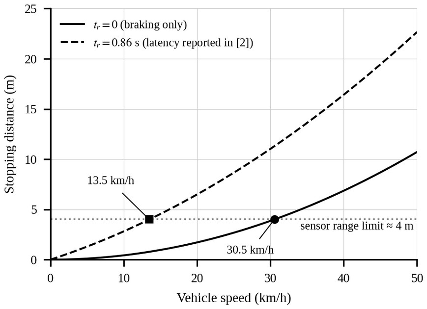
Table 5 evaluates the right-hand side of Eq. (6) for a few speeds. At 20 km/h the required stop distance with the latency of [2] is already about 6.5 m, well beyond the sensing range, whereas at 5–10 km/h it stays within roughly 1.3–2.8 m.
| Speed (km/h) | tr = 0 (m) | tr = 0.86 s (m) |
|---|---|---|
| 5 | 0.11 | 1.30 |
| 10 | 0.43 | 2.82 |
| 15 | 0.96 | 4.55 |
| 20 | 1.71 | 6.49 |
| 30 | 3.86 | 11.02 |
5.6Calibration procedure
Because dw, ds, dc, umin, n, m and Δθ depend on the particular chassis, we fix them in this order:
- 1. measure ranging error against known distances (Table 6) and choose n and the median filter;
- 2. measure the latency tr from threshold crossing to motor stop and check it against Eq. (3);
- 3. measure the deceleration a at the chosen cruising duty from observed stopping distances;
- 4. set ds from Eq. (6) with a safety margin, and set dw so that the speed ramp of Eq. (4) gives the driver time to react;
- 5. find umin, calibrate the timed turns, and set dc from the vehicle width plus a margin, with Δθ no larger than the beam width.
6Software design
6.1Firmware structure
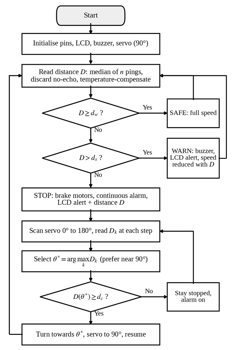
The firmware is written in C/C++ in the Arduino IDE using the Servo and LiquidCrystal libraries, plus the NewPing library for ultrasonic ranging. The control flow in Figure 4 is a small state machine with the states safe, warning, stop, scan and steer. Timing uses the millis() counter instead of blocking delays, so the buzzer pattern and LCD refresh keep running while the sensor is read. The Serial Monitor is used to log raw and filtered distances during calibration.
Algorithm 1 shows the core loop. The LCD has only 16 columns, so we show a short alert such as “OBSTACLE AHEAD” on the first row and the measured distance on the second.
Algorithm 1. Zone-based control loop
1 D ← median of n pings; ignore zero (no echo)
2 if D < d_w on m consecutive cycles then
3     if D ≤ d_s then STOP; alarm; SCAN; STEER
4     else WARN; duty ← u(D) using Eq. (4)
5 else duty ← u_max; alarm off
6 update LCD; log to Serial; wait ≥ 60 ms
6.2Implementation strategy
We plan to develop the system in phases and check each one before moving on: component selection and circuit assembly; sensor integration and Arduino programming, starting with ranging alone; adding the buzzer, LCD and motor driver; and finally testing, calibration and validation. Building the sensing, processing and actuation modules separately makes faults easier to isolate, and each module can be checked alone with the Serial Monitor before the closed loop is switched on.
7Evaluation plan and expected outcomes
This paper reports the design of the system. The prototype will be evaluated with the protocol in Table 6, which reuses quantities measured in the reviewed work: distance error and response time as in [2], dependence on surface and distance as in [4], and success rate per configuration as in [5].
| Test | Procedure | Metric |
|---|---|---|
| Ranging accuracy | Targets at known distances across the sensor range; repeated trials; flat, angled, soft and small targets | Mean error, % error, spread |
| Response latency | Approach a fixed obstacle; time from threshold crossing to alarm and to motor stop | Mean latency (s) |
| Stopping distance | Approach at several duty settings; measure the final gap | Distance vs. speed; compare with Eq. (6) |
| Avoidance success | Front, left and right obstacle patterns as in [5]; fixed number of trials each | Success rate per pattern |
| False alarms and misses | Runs with no obstacle and with hard-to-detect targets | False-alarm and miss rates |
The percentage ranging error is computed as in [2] and [4], from the mean measured distance M and the true distance Dtrue, and the avoidance success rate as in [5]:
The figures reported in [2] (0.86 s response, 12.8 % distance error), [4] (0.8–30.7 % error) and [5] (89–100 % success) are reference points, not results of this work. We expect the prototype to (i) measure distance steadily enough to place the warning and stop thresholds reliably, (ii) give the driver an immediate audible and visual alert, (iii) reduce speed gradually and stop before the stop distance is reached, and (iv) pick a clear heading when one exists. Measured values will be reported once testing is complete.
8Discussion
One scanning sensor instead of several. Reference [5] covers the front and sides with three fixed sensors. A single sensor on a servo needs fewer pins and less wiring, and there is no need to sequence several sensors so that they do not hear each other’s echoes. The cost is time: the vehicle has to be stationary during a sweep, so we scan only after a stop and use the sensor at 90° for forward monitoring.
Graded response. A warning that leaves the braking to the driver still leaves room for human error, a weakness Aliyu et al. point out in warning-only designs [2]. Braking alone, on the other hand, gives the driver no notice. Our design does both: the driver is alerted as soon as D drops below dw, and the speed is reduced gradually, as in the distance-to-speed rule of [3], before the hard stop at ds. Slowing down early also lowers the speed at which the final braking starts, which shortens the stopping distance in Eq. (6).
Path to a vehicle. The zone logic and Eqs. (6) and (7) do not depend on the specific hardware. Moving from a chassis prototype to a real vehicle would mean replacing the HC-SR04 with an automotive-grade sensor, as recommended in [4], and the L298N and DC motors with actuators suited to the vehicle. The control structure could stay the same.
9Limitations
Range and speed. The 4 m range of the HC-SR04 leaves too little braking distance at moderate or high speed (Section 5.5 and Table 5), so the design is meant for low-speed vehicles and prototypes. Reference [4] likewise recommends automotive-grade sensors for real vehicles.
Environment and target. Ranging accuracy depends on temperature (Eq. 2) and on the reflecting surface; [4] saw larger errors on rough pavement. The datasheet [9] asks for a reasonably smooth target of at least 0.5 m², and sound-absorbing targets such as fabric, very small objects and surfaces at an oblique angle may return a weak echo or none at all, and a no-echo reading is ambiguous because it also occurs when nothing is in range. Heavy rain, fog and wind may also disturb the sound waves.
Decision logic. The response depends only on fixed distance thresholds, so the system cannot tell a plastic bag from a pedestrian. Scanning stops the vehicle for the whole sweep, and a single sensor cannot watch the front and the sides at once. Steering is open-loop.
10Future scope
Machine-learning models could classify objects and predict collisions instead of relying on fixed thresholds, in line with the data-driven methods surveyed in [8]. LiDAR or radar could be fused with the ultrasonic data to get longer range, 3D mapping and better behaviour in bad weather; [2] also suggests combining ultrasonic and radar sensing. The system could be extended to autonomous navigation with path planning and mapping. IoT connectivity would allow remote monitoring, data logging and fleet or smart-city integration. The GSM location alert of [1], GPS speed measurement as in [4] and vehicle-to-vehicle communication as in [3] are natural additions.
11Conclusion
We have presented the design of an Arduino Uno based obstacle detection and collision avoidance system using a servo-mounted HC-SR04 sensor, an L298N motor driver, a buzzer and an LCD. Distance is measured from the echo time, filtered with a median of several readings and mapped to safe, warning and stop zones, with proportional slowing, braking and a scan-and-steer manoeuvre. Comparing five published prototypes supported the choice of an ultrasonic front end, multi-sample filtering and a graded response, and a stopping-distance calculation showed that the 4 m sensor range limits an ultrasonic-only system to low speeds. The next step is to build the prototype, calibrate dw, ds and dc, and report measurements from the test plan in Table 6.
Acknowledgments
The authors thank their guide, Prof. Namratha H N, Assistant Professor, Department of Computer Science (IoT, Cybersecurity Including Blockchain), Alva’s Institute of Engineering & Technology, Moodbidri, for her guidance.
References
- [1]Mahamud MS, Monsur M, Zishan MSR. An Arduino based accident prevention and identification system for vehicles. In: Proc. IEEE Region 10 Humanitarian Technol. Conf. (R10-HTC); 2017. p. 555–559.
- [2]Aliyu A, Kolo JG, Mikail OO, Agajo J, Umar B, Aguagba OI. An ultrasonic sensor distance induced automatic braking automobile collision avoidance system. In: Proc. IEEE 3rd Int. Conf. Electro-Technol. Nat. Develop. (NIGERCON); 2017. p. 570–576.
- [3]Krishnan P. Design of collision detection system for smart car using LiFi and ultrasonic sensor. IEEE Trans Veh Technol. 2018;67(12):11420–11426. https://doi.org/10.1109/TVT.2018.2870995
- [4]Gunawan TS, Effendi MR, Omar A, Kartiwi M, Ismail N. Prototype development of vehicle collision avoidance system using Arduino. In: Proc. IEEE 7th Int. Conf. Smart Instrum; 2021. p. 70–75. https://doi.org/10.1109/ICSIMA50015.2021.9526300
- [5]Xiao L. Unmanned vehicle with obstacle avoidance technology based on ultrasonic ranging. In: Proc. 8th Int. Conf. Instrum. Meas; 2018. p. 87–91. https://doi.org/10.1109/IMCCC.2018.00025
- [6]World Health Organization. Global Status Report on Road Safety 2018. Geneva: WHO; 2018.
- [7]Dahl J, de Campos GR, Olsson C, Fredriksson J. Collision avoidance: A literature review on threat-assessment techniques. IEEE Trans Intell Veh. 2019;4(1):101–113. https://doi.org/10.1109/TIV.2018.2886682
- [8]Fu Y, Li C, Yu FR, Luan TH, Zhang Y. A survey of driving safety with sensing, vehicular communications, and artificial intelligence-based collision avoidance. IEEE Trans Intell Transp Syst. 2022;23(7):6142–6163. https://doi.org/10.1109/TITS.2021.3083927
- [9]Elecfreaks. Ultrasonic ranging module HC-SR04 [product datasheet].
- [10]STMicroelectronics. L298 dual full-bridge driver. Datasheet DS0218, Rev. 5; 2023.