Robotics and Automation
Model-Based Evaluation of Dynamic Safety Control for Human–Robot Collaboration
Department of Robotics and Automation, PSG College of Technology, Coimbatore, Tamil Nadu, India
Published November 2026
Abstract
In this paper we explore how a safety controller on a robot reacts to a person passing near it when sensor data arrives to it in a delayed manner. The work is concentrated on a 2D-model involving a fixed-speed controller and dynamic controller in three situations, namely a person passing the path of the vehicle, passing diagonally toward the vehicle, and a slowly passing person, and comparing results. Each run keeps track of the minimum separation distance between the robot and person and occurrences wherein they collide, and also distance and time spent around the safety threshold (around minimum distance), besides average speed of robot. For each test, the minimum separation distance, number of collision points, time inside range and average robot speed are recorded. Both the crossing and slow-approach have no collisions under the dynamic controller. The static collision for the crossing test at -0.281 is replaced with a comfortable safety margin of 1.263m. The Diagonal still collides with minimum clearance of -0.628m. Slowing down a robot with delayed distance readings becomes safer in the simplest cases, failing when person future movement goes unnoted by the controller.
Keywords: human robot collaboration; robot safety; sensor latency; collision avoidance; braking distance; dynamic speed controller
1Introduction
Human-robot collaboration allows operators to work closely with robots; however, the direct contact is also posing a safety issue. Operators may be moving from directions the robot did not account for, and the robot may continue moving for some time before the controller acts up. A useful safety controller must take into account delays of sensing, braking ability, as well as the uncertainty in measured location of the person involved.
Speed and separation monitoring is one of the main approaches used to manage this risk. Marvel and Norcross show that a protective distance should account for human approach speed, controller response time, braking behavior, an intrusion margin, and measurement uncertainty [1]. Lucci et al. discuss how speed and separation monitoring can be used together with power and force limiting to balance safety and productivity [2]. Villani et al. and Li et al. also identify sensing, prediction, planning, and compliant control as important parts of human–robot collaboration [3], [4].
These studies motivate the present work, while a simple controller remains useful for examining the effects of delay and braking. A simple model makes it easier to see how delay and braking affect the result. For that reason, this paper presents an original model-based investigation rather than a literature review.
The central question is whether a dynamic speed-and-separation rule can reduce collision risk compared with a fixed-speed baseline when sensor delay and braking limits are included. We expected the dynamic controller to improve clearance, but also to reduce average speed. We further expected that a rule based only on current distance could fail when the person’s direction of motion changes the future closest approach.
2Research design
2.1Study variables
The study changes two factors: the controller type and the person’s motion scenario. The measured outcomes are minimum clearance, collision occurrence, time below the selected threshold, and mean robot speed. The sensor delay, the acceleration and braking as well as the sizes of the robot safety envelope and the human safety envelope are kept constant, meaning that the test only compares the controller and the scenario in a simulated model.
The controller setting has two options available, fixed speed and dynamic safety. The human motion has three options- crossing, diagonal approach and slow approach. The model uses a 0.12 s sensor delay, a maximum robot speed of 1.00 m/s, a deceleration limit of 2.50 m/s², a robot envelope radius of 0.35 m, and a human envelope radius of 0.30 m. The 1.20 m value is used as the study threshold for reporting time spent at close range.
2.2Research model
The model represents the workspace as a two-dimensional plane. The robot moves along the positive x-axis, while the person follows a prescribed constant-velocity path. Both are represented by circular safety envelopes. The model is intentionally simplified and does not represent every detail of an articulated robot, allowing the relative motion and controller decisions to be examined more directly.
The robot envelope radius is 0.35 m and the human envelope radius is 0.30 m. The controller is updated every 0.02 s, and each trial lasts 12 s. At each update, the surface-to-surface clearance is found by subtracting the two envelope radii from the distance between their centers. If the clearance goes below or reaches zero, then the collision is flagged as occurring. 1.20 m of clearance is used only as a value for experimental comparisons and is no claim to imply that any actual safety standard is met by the model.
2.3Controller design
The fixed-speed controller sends signal of 1.00m/s for the duration of the trial. Neither responding to nor taking into consideration motion, this produces fixed baseline to compare against. The clearance measurement used for the dynamic controller is 0.12 s old. The controller uses this to calculate what space is estimated to be required for the robot to react and stop and adds a little uncertainty gap. Whenever the aged clearance drops below 2.0 m or the calculated stopping requirement (plus 0.75m), target velocity is decreased to 0. Otherwise target velocity is returned to 1.0 m/s as required. The acceleration and braking limits are applied on every update than the robot slowing instantaneously.
The controller is working with a simple distance rule; it does not estimate the velocity of the person, it does not try and look into the future to predict the closest approach, it does not try and map sensor occultation. This is all of use to the experiment that we can see where the distance-only strategy breaks down.
2.4Experimental scenarios
During the crossing case, the person crosses Robot's path while starting at (5.0, 2.8)m and with velocity (0.0, -0.45)m/s. In the diagonal case, the person starts at (5.2, 3.4)m, with velocity (-0.18, -0.35)m/s, where varying lateral and longitudinal relationships are presented. In slow-approach, the person starts near the Robot at (4.8, 2.5)m, with velocity (0.0, -0.18)m/s, stays at sides of Robot.
2.5State update and decision logic
To separate robot's response from sensing delay's effect, at every time-step both the person position is advanced according to the given speed as well as the robot position according to its current speed. Then the controller is given the delayed clearance to choose a target speed and apply the acceleration and braking limits. The current value of clearance would signify a different and more optimistic controller.
Here the dynamic controller follows a simple stop-or-go rule; that is, the target speed is zero when the delayed clearance is at or below the warning boundary and it returns to its maximum value once it is above. Inevitably the actual speed changes gradually as the vehicle cannot accelerate or brake instantly. This allows the effects of the warning threshold, sensor delay and braking constraint to be isolated from one another.
2.6Outcome metrics
The minimum clearance is the minimum spatial separation in the pair of trials. This is the main safety element. The collision indicator is set to one if any collision was registered. The time below threshold describes the amount of time for which the clearance between two vessels was below 1.20 m. The mean speed was taken from more complex indices.
The metrics are best used together. A large clearance does not necessarily mean that the robot is productive, while a high average speed does not mean that the motion is safe. The trade-off is well illustrated in the case of crossing. The clearance of the dynamic controller is better, however, it remains idle for a long stretch of the trial. Having all four measurements allows to not only focus on the performance criterion, regardless whether it succeeds to collide.
3Results
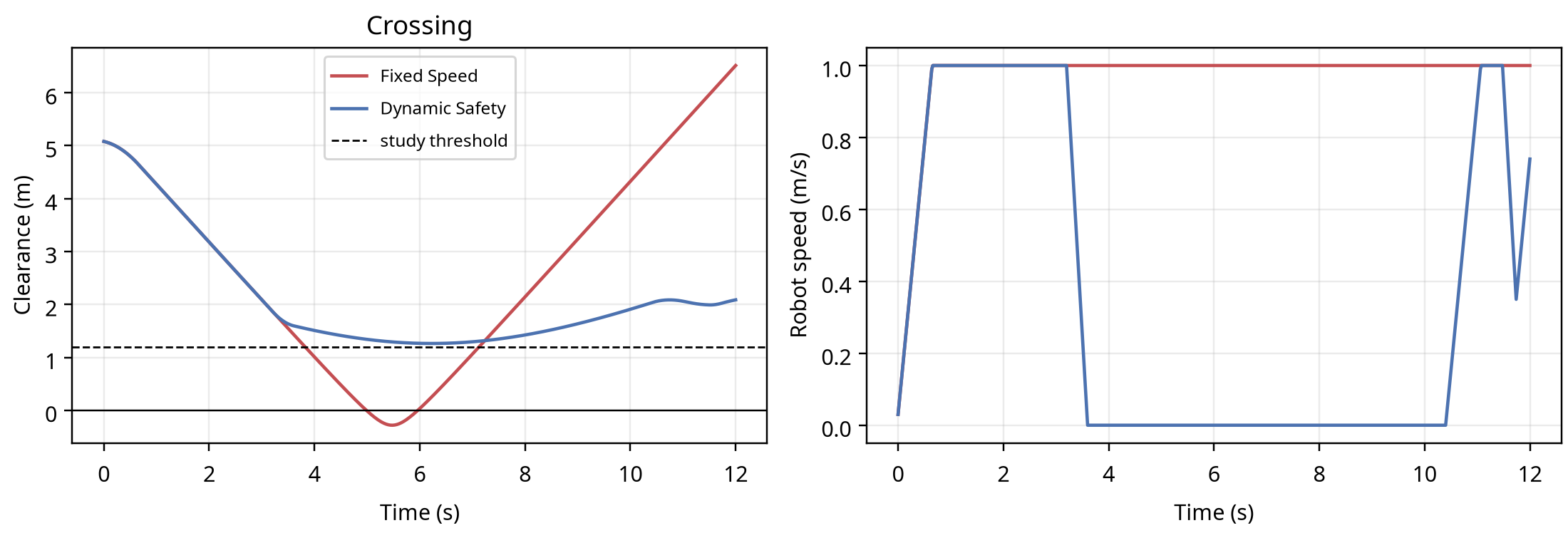
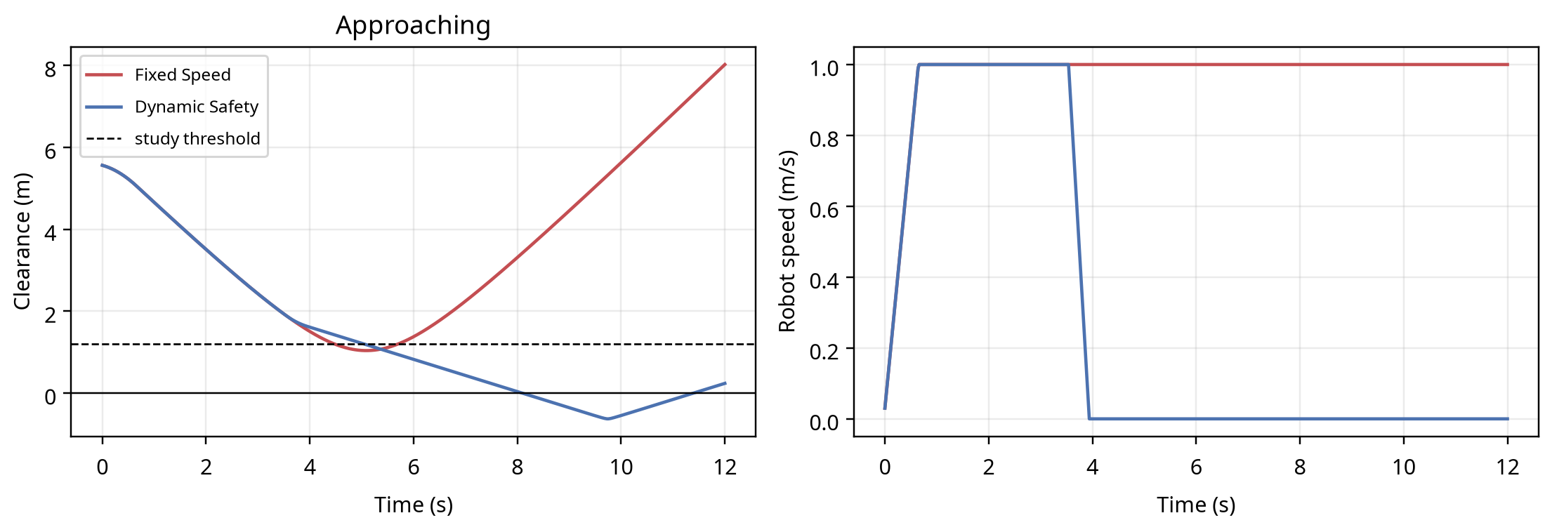
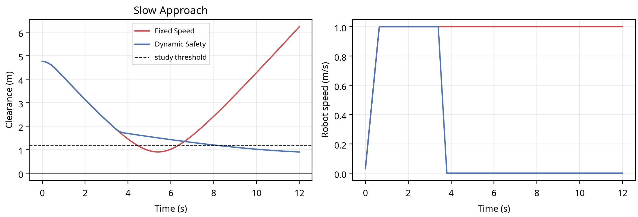
Tables 1 and 2 summarize the 6 controller-scenario. The Fixed-speed controller collides when the crossing case. In the crossing case and slow-approach case in dynamic control, collisions are avoided. In diagonal approach case in dynamic control, it still ends up in collisions.
| Scenario | Controller | Min. clearance (m) | Collision |
|---|---|---|---|
| Crossing | Fixed speed | −0.281 | Yes |
| Crossing | Dynamic safety | 1.263 | No |
| Diagonal approach | Fixed speed | 1.039 | No |
| Diagonal approach | Dynamic safety | −0.628 | Yes |
| Slow approach | Fixed speed | 0.903 | No |
| Slow approach | Dynamic safety | 0.901 | No |
| Scenario | Controller | Below threshold (s) | Mean speed (m/s) |
|---|---|---|---|
| Crossing | Fixed speed | 3.30 | 0.973 |
| Crossing | Dynamic safety | 0.00 | 0.346 |
| Diagonal approach | Fixed speed | 1.24 | 0.973 |
| Diagonal approach | Dynamic safety | 6.96 | 0.285 |
| Slow approach | Fixed speed | 1.98 | 0.973 |
| Slow approach | Dynamic safety | 4.04 | 0.273 |
The minimum clearance is increased by 1.544 m by use of the dynamic controller in the crossing case, thus collision is avoided. This improvement is at the cost of a decrease in mean speed from 0.973 m/s to 0.346 m/s. Collision is avoided by use of both controllers in the slow-approach case; however, the dynamic controller runs slower.
The dynamic controller decreases the mean speed to 0.285 m/s but at its closest range it is still at −0.628 m. It reacts to the distance, but it fails to take into consideration of its relative direction and how quickly it was coming.
3.1Scenario-level interpretation
The Figure 1 graphs show the controller's benefit. The Robot continues moving at a fixed speed till the person reaches where the distance between the safe boundary and the working space is less than 0. The dynamic controller has a two-times-bigger boundary, and a warning signal starts the moment a person enters that boundary. Following the warning signal, the robot stops a few meters before colliding with half of the safety boundary.
The diagonal scenario is more difficult with the person moving at 45 degrees since both the sideways and longitudinal separation from the collision robot. The controller sees an old distance value but due to lack of knowledge about when the person has started to turn towards the path of the collision car instead of staying or moving away from it, results in a collision and therefore shows that the limit results from the supplied distance to the collision car and lack of prediction, not only collision car speed reduction limitations.
Except for the low-approach, the effect of clearance produced from a low-speed humanoid does not appear to be dramatically increased from a low-speed non-humanoid or high-speed run at 1 m/s (see Tables 1 and 2). The low-speed person does result in them being in close proximity to the robot for a longer period of time; however, since the dynamic avoidance controller exists, overlap does not occur until much later. Given that this is the effect duration is designed to evaluate, duration will make this value higher. This is the rationale behind including duration as a useful feature in addition to the single minimum-clearance value.
3.2Safety–productivity trade-off
The mean-speed results reveal a striking difference: the dynamic controller, designed to be more attentive than humans, takes the opposite approach. Mean speed of the robot goes down in crossing case about by 64 percent while it comes low of 71 percent in diagonal and 72 percent in slow-approach cases. Such results might be appealing if it is designed for a safety purpose but also makes a convincing argument for assessing trade-offs of safety like throughput, unnecessary and task time stops made so far.
A better controller would reduce the speed to 0. It would choose a speed such that the predicted stopping distance is greater than the intrusion and be as productive as possible. The policy described would need careful validation because the command of speed control is a part of the safety function here
4Analysis and discussion
The experiment results supported the first expectation only partly, as dynamic control had improved clearance in the crossing case and avoided a crash in the slow approach case. But, it had failed in the diagonal case. The second expectation had been supported, as the dynamic control had declined mean speed in every scenario. The third one also supported because the distance-only rule failed due to unrepresentative future relative motion in the orthogonal case results.
The major reason for this error is that the delayed distance value can be similar while the outcomes can be different. The scenario is that sometimes the subject moved cross can move away from the robot path; another scenario is that the subject moved toward the robot may not do that. Since the velocities of subjects cannot be estimated and trajectories cannot be planned in advance by the controller, such problems may occur.
A clear safety-productivity trade-off can also be found in the results. The dynamic controller improved the result of crossing through early stop, but the overall mean speed was down with some 64%. A sensible practice would include figuring out a matching speed based on environment safeness instead of stop or go. The speed should depend on stopping performance, speed of human approaches, latency of the application, position uncertainties [1, 2], and the overall geometry of the application.
These findings agree overall with other research which emphasizes feeling, prediction, planning and compliant control [3], [4]. However, this study adds a small but reproducible point; the conservative delayed-distance rule fails when the approach geometry changes.
5Limitations and validity
This experiment is a computational model than a test of a real robot test a safety-rated controller. The robot is represented instead of an articulated manipulator as a translating circle and person as single circle at constant velocity, only; No test setup including measurement of reaction time (time needed for any person using safety test button (e-stop button) would do), use of light or similar safety system or even including a safety operator (similar to system with cranes or robot use) is proposed or designed by this study. No real tests on existing equipment (for this or even similar problem) and no real environment for that was tested. Any study can be designed to make any robot performance as good or bad depending on the tests. No real tests (any use case / application examples) or results from such tests are analysed/critiqued here (there are some examples by other researchers, some working with this field). Measurement delay is included but it does not, for example, include missed detections, occlusion, false positives, calibration error, communication faults or changing lighting condition. All collision is being checked at discrete time step. Higher fidelity study should run some time step convergence studies and use some continuous collision checking instead.
This is an appropriate model to compare the two defined policies under the given assumptions. It is not suitable for achieving certification or for arguing that a real workcell conforms to ISO 10218, ISO/TS 15066 or workplace policy constraints. For a safety claim in the real-world, experiments should be carried out instead.
The experimental scope is also limited, with only three deterministic motion scenarios were used, so results cannot extrapolated to every possible human trajectory beyond this limited setup. The study features no repeated stochastic trials, confidence intervals or statist tests - it is intended to be a transparent baseline. A larger study should define and justify
This circular geometry assumption is another limitation; while this is probably accurate at times, at others it probably underestimates or overestimates the clearances for a joint system in actuality. It checks clearances at discrete time steps, thus a brief contact could go unsampled if the timestep chosen is too large - higher fidelity study should reduce the time step or move collision checking to be continuous.
6Future work
Additional simulation studies would assess human velocity and find minimum required clearance distances over short lengths of time. Here, the values of the sensor delay, braking, human speeds, initial separation and uncertainty margin should all be varied across a larger range of parameters. It would perhaps be of value to move to a multi-link robot model with the links approximating human shape.
Future work will include the analysis of safety and productivity performance combined against a predictive controller. Performance metrics such as stop distance, stop time, cycle time etc. from these cases will be compiled on the baseline and the predictive controller. Comparison between the predicted stopping behaviour with measured real-life values recorded at controlled cell set-up will be done at the start of the following hardware project. Repeated test cases with different sensitivity set-ups will show the consistency of operation. Changes in system conditions such as time-step or cell faults can be assessed through detailed test runs
Varying one parameter at a time and then in combinations will produce a useful sensitivity study: delay from 0.00-0.25s, braking 1.0 - 4.0 m/s², maximum speed 0.25-1.50 m/s, speed of approach, slow to running. We would expect higher speed, delay or lower braking and higher uncertainty to require more protection distance or higher stop rate.
One other line I can suggest for the project expansion would be dividing the further developments into various stages. In the first stage the estimation of the closing speed can be implemented into the controller which may take velocity into consideration by measuring and comparing the difference of two consecutive measurements. Second a "short" horizon of minimum clearance needs to be also integrated, which estimates the minimum clearance for couple of steps/scans later. Third the noise can be added including other effects as not seeing the objects after scan, occlusions; Finally after incorporating and validating all modules on a small scale platform the same controller can be put into action and tested to compare with measured stopping behaviour into an articulated Robot.
Throughout this process by keeping original baseline at each stage will enable us more easily see where the new developed code is affecting. At the same time working within a structured form should make the debugging and identification issues would be a lot simpler. Also if possible this extension should lead to comparing the system against measured behaviour data from students operating a robot, including false stops from students and comparisons to see in which areas a controller may or may not perform better.
7Conclusion
The model-based study showed a step further. Controller that used delayed separation measurements and a conservative stopping boundary improved the crossing result for slow approach without collision but failed in diagonal case showing the usage of distance-only control is not sufficient enough for every human-motion pattern. .
A useful robot safety controller must take into account much more than just separation but also future relative motion, sensing delay, braking performance and uncertainty into its control policy. Computational models provide a reproducible benchmark to evaluate predictive controllers and clearly explain that computational results must be distinguishable from actual safety qualification.
References
- [1]Marvel JA, Norcross R. Implementing speed and separation monitoring in collaborative robot workcells. Robotics and Computer-Integrated Manufacturing. 2017;44:144–155. https://doi.org/10.1016/j.rcim.2016.08.001
- [2]Lucci N, Zanchettin AM, Rocco P. Combining speed and separation monitoring with power and force limiting for safe collaborative robotics applications. IEEE Robotics and Automation Letters. 2020;5(4):6631–6638. https://doi.org/10.1109/LRA.2020.3011852
- [3]Villani V, Pini F, Leali F, Secchi C. Survey on human–robot collaboration in industrial settings. Mechanism and Machine Theory. 2019;131:248–266. https://doi.org/10.1016/j.mechmachtheory.2018.10.009
- [4]Li W, et al. Safe human–robot collaboration for industrial settings: A survey. Journal of Intelligent Manufacturing. 2024. https://doi.org/10.1007/s10845-023-02159-4
- [5]Liu H, et al. Collision-free human–robot collaboration based on context awareness. Robotics and Computer-Integrated Manufacturing. 2021.